Chapter 2
39
BIOS Setup Utility
The BIOS Setup Utility is a hardware configuration program built into your system’s BIOS (Basic Input/Output
System). Since most systems are already properly configured and optimized, there is no need to run this utility.
The BIOS setup utility stores basic settings for your system. You will need to run this utility if you encounter
configuration problems. Refer to Chapter 4 Troubleshooting when problem arises.
Entering BIOS Setup
Power on the system to start the system POST process. During bootup, press
F2
to enter the BIOS setup
screen.
NOTE:
You must press
F2
while the system is booting. This key does not work during any other time.
BIOS Setup Primary Menus
There are several tabs on the setup screen corresponding to the six primiary BIOS menus.
T
Information
T
Main
T
Security
T
Boot
T
Exit
In the descriptive table following each of the screen illustrations, settings in
boldface
are the default and
suggested parameter settings.
BIOS Setup Navigation Keys
Note the following reminders when moving around the Setup utility.
T
Use the
Left
and
Right
arrow keys to move to the next page or to return to the previous screen.
T
Use the
Up
and
Down
arrow keys to select an item.
T
Use the
+
and
-
keys to select an option.
NOTE:
You can configure a parameter that is enclosed in square brackets. Grayed-out items have fixed
settings and are not user-configurable.
T
Use the
Enter
key to display a submenu screen.
NOTE:
When a parameter is preceeded by an
arrow
or (
>
), it means that a submenu screen is available.
T
Press
F1
for General Help using the BIOS setup.
T
Press
F9
to load the default configuration.
T
Press
F10
to save changes and close the BIOS setup.
T
Press
Esc
to close the BIOSe setup.
NOTE:
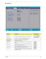
The parameters on the screens shown in this Guide display default system values. These values may
not be the same as those in the system. System information is subject to different models.
System Utilities
Chapter 2
Summary of Contents for Aspire 4310
Page 10: ...x ...
Page 56: ...46 Chapter 2 ...
Page 90: ...80 Chapter 3 19 Carefully detach the RTC battery from the SD card slot ...
Page 118: ...108 Chapter 4 ...
Page 119: ...Chapter 5 109 System Block Diagram System Block Diagram and Connector Locations Chapter 5 ...
Page 122: ...112 Chapter 5 Switch Setting Short G68 to clear password ...
Page 126: ...116 Chapter 4 Aspire 4710 4310 Exploded Diagram ...
Page 155: ...145 Appendix A ...
Page 156: ...Appendix A 146 ...
Page 164: ...154 Appendix C ...


