


SuperWorkstation 5039D-I User's Manual
Chapter 4: Motherboard Connections
35
36
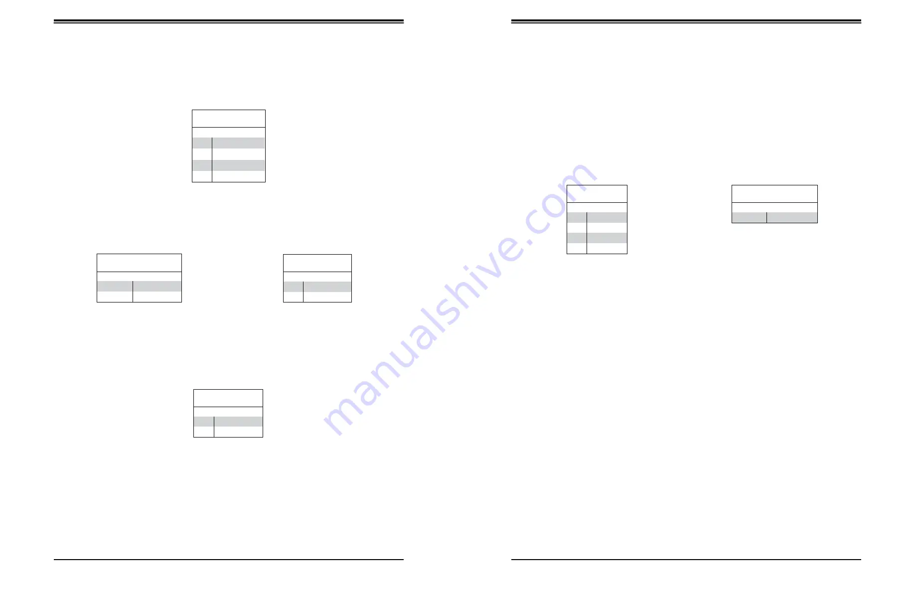
4-pin BMC External I
2
C Header
A System Management Bus header for IPMI 2.0 is located at JIPMB1. Connect the appropriate
cable here to use the IPMB I
2
C connection on your system.
Unit Identifier Switch/UID LED Indicator
A rear Unit Identifier (UID) switch and a rear UID LED (LED1) are located next to the VGA
port on the motherboard. The front UID switch and the front UID LED are both located on the
Front Panel Control (JF1) (with the front UID switch on pin 13, and the front LED on pin 7
of JF1). When you press the front or the rear UID switch, both front and rear UID LEDs will
be turned on. Press the UID switch again to turn off the LED indicators. The UID Indicators
provide easy identification of a system unit that may be in need of service.
Note:
UID can also be triggered via IPMI on the motherboard. For more information on IPMI,
please refer to the IPMI User's Guide posted on our website at http://www.supermicro.com.
Overheat/Fan Fail LED Header
The JOH1 header is used to connect an LED indicator to provide warnings of chassis
overheating and fan failure. This LED will blink when a fan failure occurs.
Chassis Intrusion
A Chassis Intrusion header is located at JL1 on the motherboard. Attach the appropriate cable
from the chassis to inform you of a chassis intrusion when the chassis is opened.
Chassis Intrusion
Pin Definitions
Pin#
Definition
1
Intrusion Input
2
Ground
Overheat LED Header
Status
State
Definition
Solid
Overheat
Blinking
Fan Fail
Overheat LED
Pin Definitions
Pin#
Definition
1
5vDC
2
OH Active
External I
2
C Header
Pin Definitions
Pin#
Definition
1
Data
2
GND
3
Clock
4
NC
UID Switch
Pin Definitions
Pin#
Definition
1
Ground
2
Ground
3
Button In
4
Ground
UID LED
Pin Definitions
Color
Status
Blue: On
Unit Identified


