background image

AcerPower 6000 User’s Guide

4-12

4.5

Upgrading the CPU

The board supports a Pentium II processor or a Celeron processor.  Both
processors come in a new enclosed packaging technology called S.E.C.
(Single-Edge Contact) cartridge.  The only difference between the two is that the
Pentium II processor comes with 256-KB or 512-KB built-in second-level cache,
while the Celeron processor comes only with an internal cache.  Both are capable
of increasing the performance of 32-bit software and multimedia applications.

4.5.1

Removing the Processor Card

Observe the ESD precautions when installing or
removing a system component.  See section 4.1.1.

Before you can replace or upgrade your processor, you need to remove the
previously installed processor on the system board.

Follow these steps to remove the processor card:
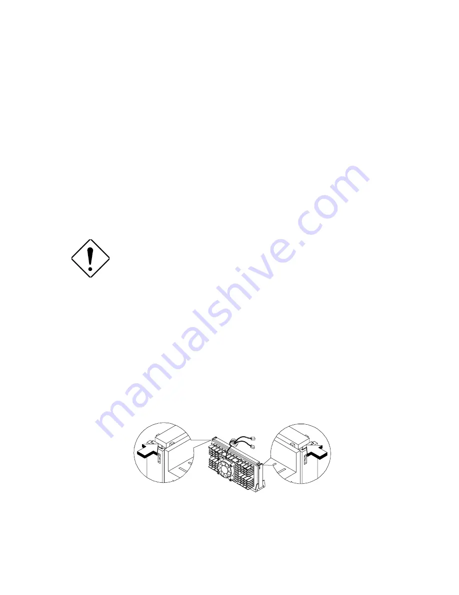
1.


Press the latches on both sides of the processor to release it from the retention
mechanism.  You will hear a click sound once the latch is released.

Figure 4-9 Pressing the Latches

Summary of Contents for AcerPower 6000

Page 1: ...tions Electrostatic discharge ESD can damage your processor disk drives expansion boards and other components Always observe the following precautions before you install a system component 1 Do not re...

Page 2: ...tch located on the rear panel If the system main power switch is not available unplug the system 2 Open the system according to the instructions in section 4 2 1 3 Follow the ESD precautions in sectio...

Page 3: ...rds or peripherals that you removed earlier 4 Replace the system cover 5 Connect the necessary cables and turn on the system 4 2 Removing and Replacing the Housing Cover Before you proceed make sure t...

Page 4: ...Set the screws aside You will need them when replacing the housing cover Figure 4 1 Removing the Screws 4 Push the housing cover slightly backward as indicated in Figure 4 2 5 Pull the housing cover...

Page 5: ...nal Components 4 5 4 2 2 Replacing the Housing Cover 1 Replace the housing cover as shown in Figure 4 3 Figure 4 3 Replacing the Housing Cover 2 Secure the housing cover with the necessary screws Figu...

Page 6: ...lot s on the system board 2 Remove the bracket on the housing opposite to the empty PCI slot 3 Insert a PCI card into the slot Make sure that the card is properly seated 4 Secure the card to the housi...

Page 7: ...1 Remove all PnP cards installed in the system if any 2 Install non PnP ISA cards 3 Turn on the system 4 Use Windows 95 or ICU to manually assign the appropriate IRQs to the cards This ensures that BI...

Page 8: ...able to a maximum of 256 MB via two 168 pin DIMM sockets on board These DIMM sockets accept DRAMs with 8 16 32 64 and 128 MB capacities 60 ns nanoseconds or less access time and with ECC See Figure 2...

Page 9: ...l Memory 8 MB 8 MB 16 MB 16 MB 32 MB 32 MB 64 MB 64 MB 128 MB 128 MB 8 MB 8 MB 16 MB 16 MB 32 MB 32 MB 64 MB 64 MB 128 MB 128 MB 8 MB 16 MB 24 MB 16 MB 32 MB 48 MB 32 MB 64 MB 96 MB 64 MB 128 MB 192 M...

Page 10: ...e socket 3 Press the DIMM into the socket until the clips lock into the DIMM Figure 4 7 Installing a DIMM The DIMM socket is slotted to ensure proper installation If you insert a DIMM but it does not...

Page 11: ...n both sides of the socket outward to release the DIMM 2 Gently pull the DIMM out of the socket Figure 4 8 Removing a DIMM 4 4 3 Reconfiguring the System The system automatically detects the amount of...

Page 12: ...an internal cache Both are capable of increasing the performance of 32 bit software and multimedia applications 4 5 1 Removing the Processor Card Observe the ESD precautions when installing or removi...

Page 13: ...ing a Processor Card Observe the ESD precautions when installing or removing a system component See section 4 1 1 Before you proceed make sure that there is no processor installed in the CPU connector...

Page 14: ...lling the Retention Mechanism 3 Remove the processor card from its protective packaging Make sure that the latches on the sides of the module are not pressed 4 Remove the thermal tape protector at the...

Page 15: ...into the CPU cartridge and then push the metal bracket s handle to lock the metal bracket into place Figure 4 14 Locking the Metal Bracket 7 With the processor card golden fingers pointing downward a...

Page 16: ...wn the processor until the golden fingers completely fit into the connector and the latches on the sides lock the processor into place Figure 4 16 Locking the Processor 10 Connect the 3 pin and 2 pin...

Page 17: ...5 3 Installing the Celeron CPU Observe the ESD precautions when installing or removing a system component See section 4 1 1 Before you proceed make sure that there is no processor installed in the CP...

Page 18: ...n the system board Figure 4 18 Installing the Retention Mechanism 3 Remove the Celeron processor from its protective packaging 4 Attach the heatsink on top of the Celeron processor 5 Align the fastene...

Page 19: ...l the golden fingers completely fit into the connector 8 Snap the retention cover into place as shown in the figure below Figure 4 20 Installing the Celeron Processor The heatsink becomes very hot whe...

Page 20: ...upport additional serial devices without using up your system resources To connect a USB device simply plug the device cable into a USB port marked on the rear panel See the following figure Figure 4...

Reviews: