


AcerPower 6000 User’s Guide
4-10
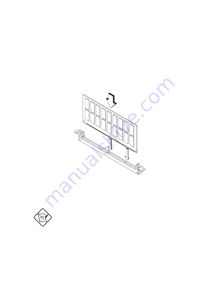
4.4.1
Installing a DIMM
1.
Open the clips on the socket.
2.
Align the DIMM with the socket.
3.
Press the DIMM into the socket until the clips lock into the DIMM.
Figure 4-7 Installing a DIMM
The DIMM socket is slotted to ensure proper
installation. If you insert a DIMM but it does not fit
easily into the socket, you may have inserted it
incorrectly. Turn the DIMM around and try to insert
it again.


