1-
18
Service Guide
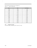
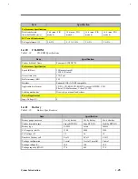
The following table lists all possible memory configurations.
Table 1-14
Memory Configurations
Slot 1
Slot 2
Total Memory
8 MB
0 MB
8 MB
0 MB
8 MB
8 MB
8 MB
8 MB
16 MB
16 MB
0 MB
16 MB
0 MB
16 MB
16 MB
16 MB
8 MB
24 MB
8 MB
16 MB
24 MB
16 MB
16 MB
32 MB
32 MB
0 MB
32 MB
0 MB
32 MB
32 MB
32 MB
8 MB
40 MB
8 MB
32 MB
40 MB
32 MB
16 MB
48 MB
16 MB
32 MB
48 MB
32 MB
32 MB
64 MB
1.4.9
Second-Level Cache
This notebook supports 256KB pipeline burst second-level (L2) cache.
Summary of Contents for AcerNote Light 370P
Page 6: ...vi ...
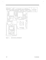
Page 26: ...1 8 Service Guide Figure 1 5 Main Board Layout Bottom Side ...
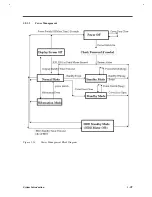
Page 49: ...System Introduction 1 31 1 5 1 3 Power Management Figure 1 14 Power Management Block Diagram ...
Page 55: ...System Introduction 1 37 1 6 System Block Diagram Figure 1 15 System Block Diagram ...
Page 64: ...Major Chips Description 2 7 2 2 5 Pin Diagram Figure 2 4 M1521 Pin Diagram ...
Page 99: ...2 42 Service Guide 2 5 3 Pin Diagram Figure 2 10 C T 65550 Pin Diagram ...
Page 117: ...2 60 Service Guide Figure 2 12 Functional block diagram CardBus Card Interface ...
Page 119: ...2 62 Service Guide Figure 2 14 PCI to CardBus terminal assignments ...
Page 135: ...2 78 Service Guide 2 7 3 Pin Diagram Figure 2 16 NS87336VJG Pin Diagram ...
Page 145: ...2 88 Service Guide 2 8 2 Pin Diagram Figure 2 17 YMF715 Block Diagram ...
Page 185: ...Disassembly and Unit Replacement 4 5 Figure 4 3 Disassembly Sequence Flowchart ...
Page 209: ...B 2 Service Guide ...
Page 210: ...Exploded View Diagram B 3 ...

