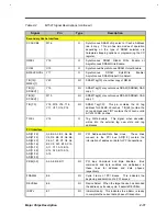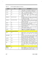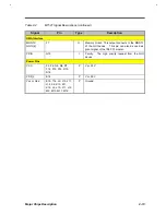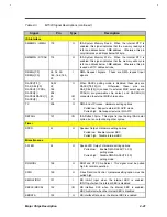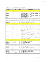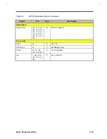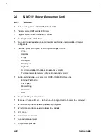
Major Chips Description
2-25
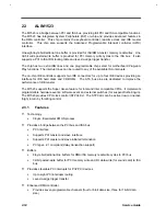
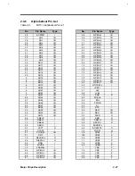
2.4.2
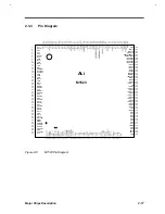
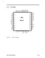
Pin Diagram
Vss
AD23
AD22
AD21
AD20
AD19
AD18
AD17
AD16
CBEJ2
VDD5
FRAMEJ
IRDYJ
TRDYJ
DEVSELJ
PAR
CBEJ1
SMIJ
Vss
AD15
AD14
AD13
AD12
AD11
AD10
1
2
3
4
5
6
7
8
9
10
11
12
13
14
15
16
17
18
19
20
21
22
23
24
25
GPIOC3
GPIOC2
GPIOC1
GPIOC0
GPIOA7
GPIOA6
GPIOA5
GPIOA4
GPIOA3
GPIOA2
GPIOA1
GPIOA0
Vss
CLK32
SEL1
SEL0
VDD5
DISPLAY
CCFT
FPVEE
SPKCTL
SQWO
SLED
DRQ
CRT
75
74
73
72
71
70
69
68
67
66
65
64
63
62
61
60
59
58
57
56
55
54
53
52
51
ALi
M7101
Figure 2-7
M7101 Pin Diagram
Summary of Contents for AcerNote Light 370P
Page 6: ...vi ...
Page 26: ...1 8 Service Guide Figure 1 5 Main Board Layout Bottom Side ...
Page 49: ...System Introduction 1 31 1 5 1 3 Power Management Figure 1 14 Power Management Block Diagram ...
Page 55: ...System Introduction 1 37 1 6 System Block Diagram Figure 1 15 System Block Diagram ...
Page 64: ...Major Chips Description 2 7 2 2 5 Pin Diagram Figure 2 4 M1521 Pin Diagram ...
Page 99: ...2 42 Service Guide 2 5 3 Pin Diagram Figure 2 10 C T 65550 Pin Diagram ...
Page 117: ...2 60 Service Guide Figure 2 12 Functional block diagram CardBus Card Interface ...
Page 119: ...2 62 Service Guide Figure 2 14 PCI to CardBus terminal assignments ...
Page 135: ...2 78 Service Guide 2 7 3 Pin Diagram Figure 2 16 NS87336VJG Pin Diagram ...
Page 145: ...2 88 Service Guide 2 8 2 Pin Diagram Figure 2 17 YMF715 Block Diagram ...
Page 185: ...Disassembly and Unit Replacement 4 5 Figure 4 3 Disassembly Sequence Flowchart ...
Page 209: ...B 2 Service Guide ...
Page 210: ...Exploded View Diagram B 3 ...

