


Chapter 5
47
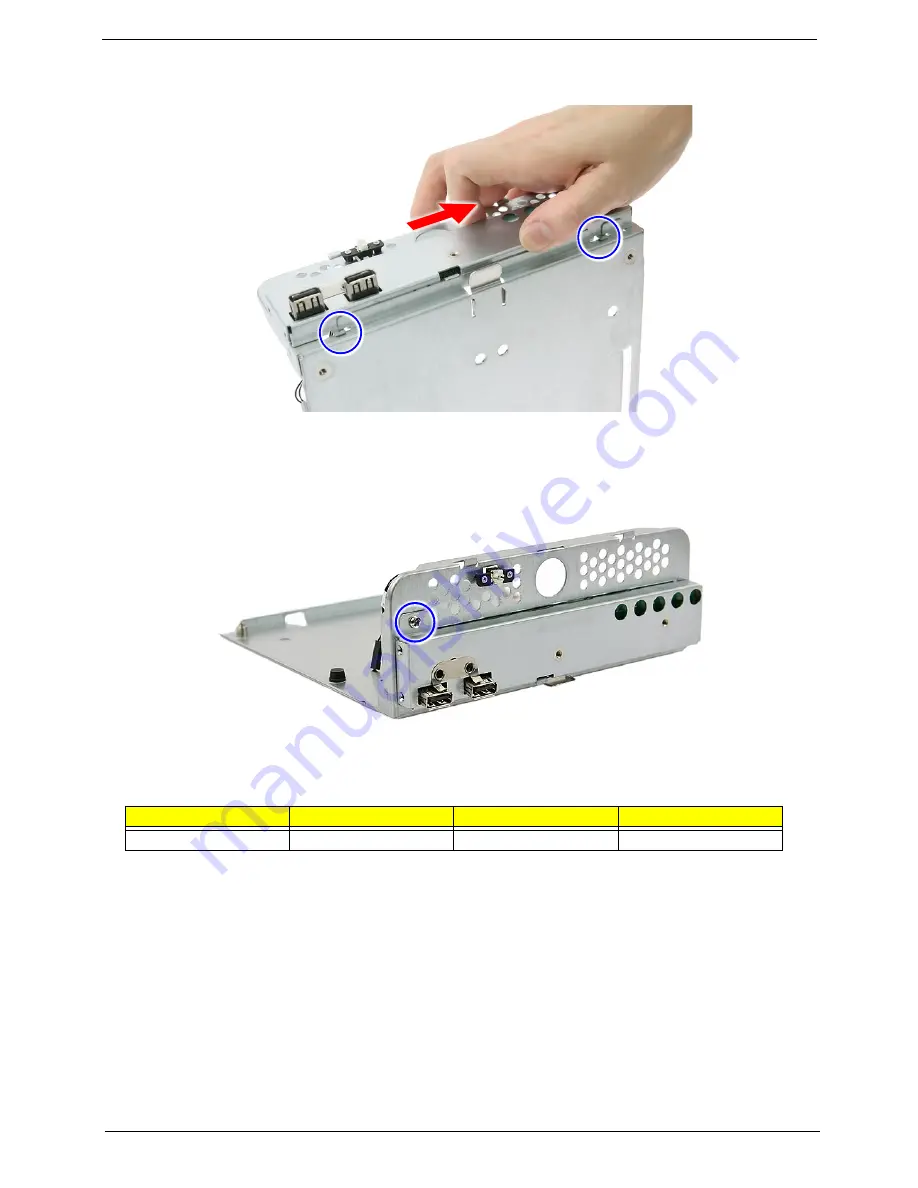
4.
Slide the front I/O board bracket slightly to the right and make sure that it is securely attached to the
mainboard tray.
5.
Secure the front I/O board bracket to the mainboard tray with one screw.
Screw (Quantity)
Color
Torque
Part No.
M3-0.5*4 NI (1)
Chrome
5.1 to 6.9 kgf-cm
86.1A524.4R0
Summary of Contents for AC100
Page 1: ...AC100S Service Guide PART NO PRINTED IN TAIWAN ...
Page 7: ...Chapter 1 1 Exploded view System components Chapter 1 ...
Page 14: ...8 Chapter 3 Front inner view No Icon Component 1 Lock 2 HDD carriers 3 Power button ...
Page 19: ...Chapter 3 13 System block diagram ...
Page 20: ...14 Chapter 3 ...
Page 40: ...34 Chapter 5 12 Pull out the mainboard tray completely ...
Page 50: ...44 Chapter 5 3 Pull the power button cable module through the opening on the mainboard tray ...
Page 77: ...Chapter 5 71 7 Close the front panel door ...
Page 78: ...72 Chapter 5 ...
Page 112: ...106 Chapter 8 ...


