


ARM ASSEMBLY FOR WALL/COLUMN MOUNT
Please note that the arm support structure is inside a tube. The hose for the arm is on the outside of the tube. First
remove the hose from the tube. Take care not to damage the hose. Patience is the best assurance. Secondly, remove the
support structure from inside the tube. Each arm requires several components. Lay out the components to be sure that
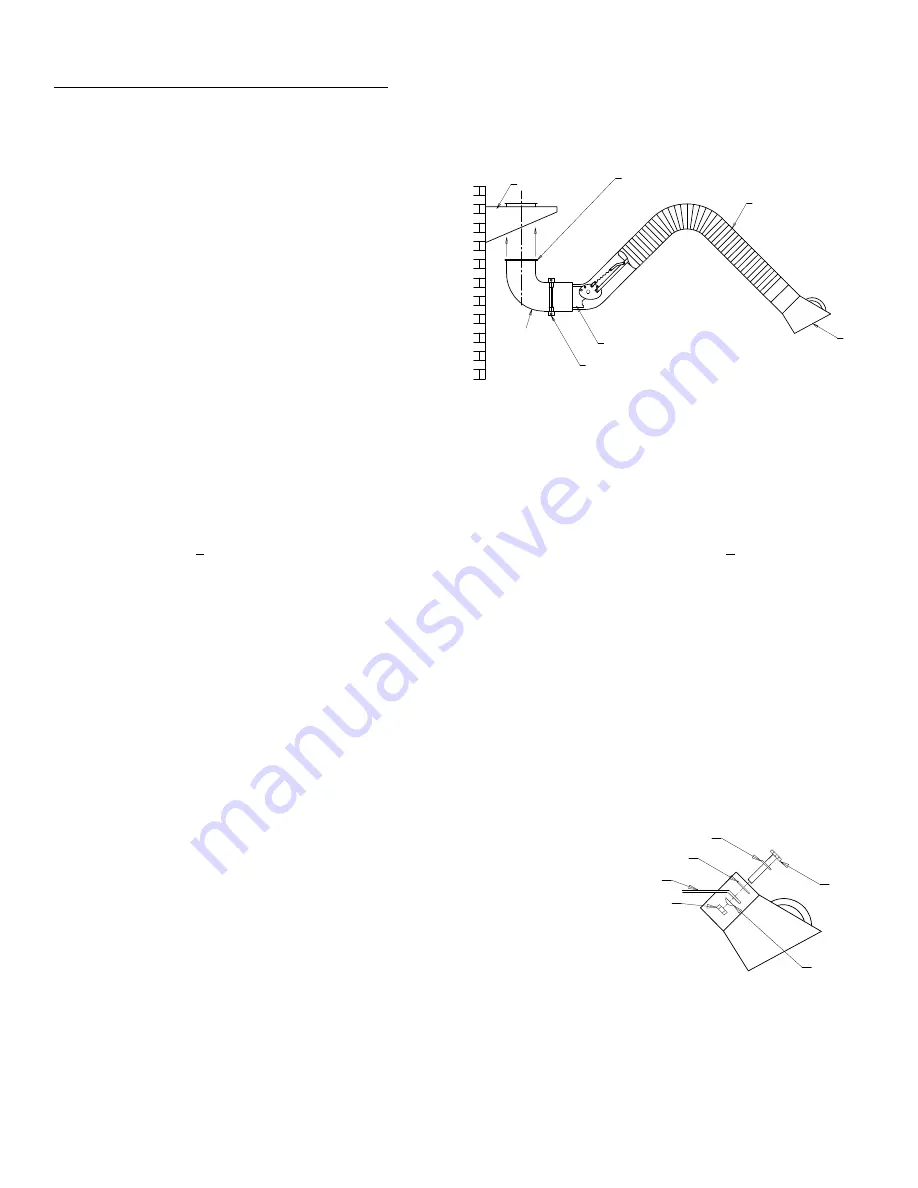
you have received all the correct components. See figure 1 for arm layout.
90^ Elbow
Clamp with
Gasket
White bracket
Hood
Hose 6" DIA
Black nylon swivel collar
Mounting bracket
Figure 1
6
A. Arm complete with hood, hose & base.
B. Swivel
90
°
elbow with mounted nylon pivot ring.
C. Mounting bracket (Not used for arms on duct mount or
booms)
D. Bag of hardware
E. 8 hole rubber gasket
F. Connection flange (MODEL 75-800)
NOW YOU ARE READY TO ASSEMBLE AND ADJUST
THE ARM. SEE ENCLOSED DRAWINGS AND
INFORMATION.
1. Locate your desired area to mount the arm. The support structure should be solid and fairly strong. Please note that
the arm will develop stress on the support structure when the user pulls and positions the arm during use.
2. Using the mounting bracket, position the bracket on the support structure and, using a level, mark the holes in
preparation for attaching the bracket. Be sure the bracket is as square and as level as you can make it. Use the level
for this. Now mount the bracket and be sure it is secure.
3. Slide the hose away from the white base bracket. Please note that there is a bolt with a red painted head. This bolt is
in a hole marked 2. Remove this bolt and pivot the white bracket 90 degrees so the hole marked 1 will line up with the
hole in the bracket. Replace the red bolt and nut and bring to a snug fit. (See figure 2.)
4. Attach the 90 degree elbow to the white arm bracket. Note that the elbow and the white bracket have a small mating
flange. There is a rubber gasket that seals the flanges of the elbow and the white bracket. Install the steel metal
clamp over the rubber gasket and flanges. BE SURE THAT THE ELBOW AND ARM ARE IN A PERFECT
VERTICAL POSITION BEFORE TIGHTENING THE CLAMP. The arm should be vertical and the elbow is also
vertical (See Figure 2).
5. With assistance, mount the assembled arm and elbow to the mounting bracket. The elbow has a mounted 8 hole
black nylon swivel collar. Locate and bolt the arm, elbow, and black nylon collar to the bracket by the 8 holes.
Tighten the bolts to hold the elbow to the mounting bracket. DO NOT OVER TIGHTEN THE BOLTS. Be sure the
elbow can swivel freely at the bracket.
6. The arm will need final adjustment/tuning for easiest movement and to stay in place upon positioning. You will find
friction pads and adjustment pivot joints in four (4) places, 1) Pivot point at the white bracket, 2) Pivot point at the
center of the arm. 3 & 4) Pivot points at the hood location. Only
put enough tension on these pivot joints to hold the arm in any
position it is placed. The arm final adjustment is key to the arm
being user friendly. DO NOT OVER TIGHTEN THE PIVOT JOINT
FRICTION DISKS. Depending on arm usage and movement,
occasional adjustments may be required. Based on the arms
application, cleaning of the internal support structure may require
scheduled cleaning.
7. Extend the arm out and slide the hose over the arm. Clamp the
hose to the white bracket using the clamp provided.
Bolt
Concave
Washer
Nut
Hood arm bar
Large steel washer
Small steel washer
8. For attachment of the connection flange, see page 10 on connection flange assembly for MODEL 75-800.
Summary of Contents for 73-501
Page 13: ...13...


