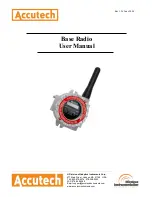
Accutech WI-BR-I-XP User Manual Download Page 3


Rev 1.56 

User Manual 

Base Radio 

Models WI-BR-I-XP, WI-BR-I-XP-
MOD


and WI-BR-I-XP-AO


Versions 1.56 or later


© Adaptive Instruments Corp., 2005. 

Printed in the USA 

Important Information to the User


!


• 

Changes or modifications not expressly approved by Adaptive Instruments, LLC 
may void the user’s authority to operate the equipment. 


• 

This device complies with Part 15 of the FCC Rules. Operation is subject to the 
following two conditions: 1) this device may not cause harmful interference, and 
2) this device must accept any interference received, including interference that 
may cause undesired operation. 


• 

This device is for mobile and fixed use only (not portable or body-worn). A 
separation distance of 20cm must be maintained at all times between the antenna 
and the body of the user and bodies of nearby persons.


• 

If the Wireless Instrumentation Manager (RF Server) software is shutdown, the 
RS-485 network 

MUST be physically disconnected 

from the PC as the serial 

port is no longer being controlled by the software and may disrupt communica-
tions between the Base Radio(s) and Analog/Digital Output Module(s).


• 

This device has been designed to operate with an antenna having a maximum 
gain of 9 dBd.  Antenna having a higher gain is strictly prohibited per regulations 
of Industry Canada. The required antenna impedance is 50 ohms.


• 

To reduce potential radio interference to other users, the antenna type and its gain 
should be so chosen that the equivalent isotropically radiated power (EIRP) is not 
more than that required for successful communication.  


• 

The installer of this radio equipment must ensure that the antenna is located or 
pointed such that it does not emit RF field in excess of Health Canada limits for 
the general population; consult Safety Code 6, obtainable from Health Canada’s 
website 

www.hc-sc.gc.ca/rpb

.


!


FCC Certification


• 

This product is a frequency hopping RF transceiver module for the 900MHz ISM 
band, designed to meet FCC 15.247, and is used in industrial control and moni-
toring applications.


• 

The antenna is factory installed and 

MUST NOT

 be removed or modified by 

user.


!


!


NOTE


• 

This document cannot be changed without prior FM approval.


Accutech


A Division of Adaptive Instruments Corp. 

577 Main Street 

· 

Hudson, MA 01749 USA 

TEL: 800-879-6576 

· 

978-568-0500 

FAX: 978-568-9085 
Email: 

[email protected]


Web: 

www.accutechinstruments.com


Summary of Contents for WI-BR-I-XP

Page 1: ...____________________________________________________________________________________________ A Division of Adaptive Instruments Corp 577 Main Street Hudson MA 01749 U S A TEL 800 879 6576 978 568 0500...

Page 2: ......

Page 3: ...g Digital Output Module s This device has been designed to operate with an antenna having a maximum gain of 9 dBd Antenna having a higher gain is strictly prohibited per regulations of Industry Canada...

Page 4: ......

Page 5: ...nu Map 9 4 3 The Number of Wireless Instruments Setting NUM WI 9 4 4 Setting the User Password 9 Section 5 Configuring the RF Communications ______________ 10 5 1 RF Channel Selection 10 5 2 RF Baud R...

Page 6: ...Radio Power UP and Operations Sequence 8 4 2 The Read Only Sequence 8 4 3 Overall Configuration Menu Map 9 4 4 Menu Map to Number of Wireless Instruments Setting 9 4 5 Menu Map to Password Setting 9 5...

Page 7: ...setting as well as how to configure this setting Section 5 Configuring the RF Communications This section covers the setup of the Base Radio RF Communications which allow the Base Radio to detect and...

Page 8: ...ng List and check off the actual equipment received If you have any questions on your shipment please call your Accutech Rep resentative Upon receipt of shipment inspect the container for any signs of...

Page 9: ...s with which you wish to communicate Number of WI s to the number of Field Units to communi cate with this Base Radio 7 Configure the Modbus settings WI BR I XP MOD only 8 Configure the Analog Output...

Page 10: ...ll possible variations The final installation must be made at the discretion and approval of the user You must be the judge of the actual installation 3 1 1 Base Radio Positioning Correct positioning...

Page 11: ...Wiring Schematic Explosions may result in death or serious injury Do not remove the instrument cover in explosive atmospheres when power and communications are on Warning To begin the electrical inst...

Page 12: ...n RS 485 to RS 232 converter the A Tx Rx and B Tx Rx wires may need to be crossed for correct operation Please see the converter s user manual for further instructions Accutech offers an optically iso...

Page 13: ...this end unit is done within the converter In a multiple unit daisy chain application the end unit is shown in Figure 3 8 Termination of an end unit is done by placing a resistor across the A and B wi...

Page 14: ...power up the Base Radio will display a Power Up Sequence and then go into an Operations Sequence These Sequences are shown in Figure 4 1 below 4 1 Base Radio Displayed Messages NOTE During configurati...

Page 15: ...e if you had 10 Field Units to be set to this Base Radio you would set the number of wireless instruments to 10 When you returned to the operations sequence you would then read BASE OK and 10 WI if al...

Page 16: ...are three selectable settings with approximate update times and ranges listed below 4 8K Baud rate of 4 8 Kbaud Update every 20 seconds Range of 3000ft Line of Sight 19 2K Baud rate of 19 2 Kbaud Upda...

Page 17: ...2 Get Com Event Log 6 3 5 Command 17 Report Slave ID 6 3 6 Command 43 Read Device ID 6 1 Base Radio Setup The purpose of this section is to guide the user through the configuration of the Base Radio i...

Page 18: ...io with Modbus device ID 001 Field Unit with RF ID 1 is found at Modbus device ID 002 Field Unit with RF ID 2 is found at Modbus device ID 003 Field Unit with RF ID 3 is found at Modbus device ID 004...

Page 19: ...ters lo cated at this device ID for this Base Radio Each Field Unit communicat ing with this Base Radio is then located at device ID X where X is the RF ID of the Field Unit the Device ID of the Base...

Page 20: ...Units were on the Base Radio s network the maximum Modbus device ID would be 242 If the register mapping mode REGMODE is selected a Field Unit s data may be accessed with the Modbus Read Holding Regis...

Page 21: ...Radio holding registers for all mapping modes i e Device ID and Register mapping modes 6 3 1 1 1 Base Radio Device Type Registers The Base Radio Device Type value is 255 This is the only possible valu...

Page 22: ...racted 8 4 2 and 1 and these numbers corre spond to Field Units with RF IDs 1 2 3 and 4 In another example say the On Offline Status holding register contains the value 6 We can subtract 4 to get 2 Th...

Page 23: ...t 100 PSID 18 Split Differential Pressure Field Unit 100 PSID 19 Differential Pressure Field Unit 300 PSID 20 Split Differential Pressure Field Unit 300 PSID 6 3 1 2 2 Field Unit Device Status Registe...

Page 24: ...formation is returned for any device ID that the Base Radio has control of i e including Field Units mapped to virtual device IDs when operating in the device ID mapping mode See Section 6 2 6 3 3 Com...

Page 25: ...e type device status and a run indicator status byte The 16 bit device type and device status words are identical to those held in the holding registers The run indicator status byte is 255 0xFF hex i...

Page 26: ...m For example if the Base Radio is out putting 4mA but the user s system is indicating the Base Radio is only outputting 3 85mA then the user would enter a 0 15mA in the 4mA trim menu which would in t...

Page 27: ...Menu Map to the Failsafe Output Setting The Single output option allows the user to select one of the Field Units on the Base Radio Network and then have that Field Units Input 1 ranged over the 4 20m...

Page 28: ...I XP AO Serial Modbus RTU Binary WI BR I XP MOD over RS 485 Modbus over TCP IP via optional converter Accuracy 4 20 mA is Opto isolated Isolation voltage 800 V 9 V minimum loop voltage 4 uA resolutio...

Page 29: ...ode The NEXT button is then used to step through menu options and the ENTER button is used to enter a submenu of what is displayed on the LCD at that time If no button is pressed within a 30 second pe...

Page 30: ...Accutech Wireless Base Radio User Manual 24 Rev 1 56 Base Radio Menu Map Appendix B...

Page 31: ......

Page 32: ...and beverage primary materials processing and energy industries In addi tion to the wireless product line Accutech also offers a tradi tional wired line of temperature pressure and differential pressu...

Reviews: