


Rev 1.56
5
3.2: Electrical Installation
In this section wiring instructions are discussed for the various setup capa-
bilities of the Base Radio. The subsections are as follows:
3.2.1: Electrical Specifications
3.2.2: Wiring Power to the Base Radio
3.2.3: Wiring RS-485 to the Base Radio
3.2.4: Wiring an RS-232 Converter to the Base Radio
3.2.5: Wiring the Analog Output Loop
3.2.6: Terminating the Base Radio
3.2.7: Grounding the Base Radio Housing
Warning
Remember to turn off all power
BEFORE
hook-
ing up any wires!
!
!
3.2.1: Electrical Specifications
•
24VDC Power Supply with 0.5 Amp minimum output
Recommend 22AWG Power Supply wire
•
2 Wire RS-485 Serial Communications Cable
Recommend Belden 3105A shielded and protected 22AWG or
equivalent
•
120 W, ± 5%, ¼ W resistor for RS-485 termination
•
RS-485 to RS 232 converter B&B model 485LDRC9 or equivalent
•
8 AWG bare or green covered grounding cable for housing ground
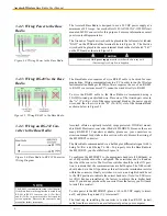
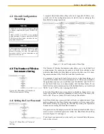
In Figure 3.2, an overall wiring schematic is shown. Note that the ground-
ing screw is located on the outside of the Base Radio housing.
Figure 3.2: Overall Wiring Schematic
Explosions may result in death or serious injury.
Do not remove the instrument cover in explosive
atmospheres when power and communications are
on.
Warning
!
!
To begin the electrical installation first remove the explosion proof hous-
ing cover from the Base Radio, if you have not already done so. Point the
Base Radio antenna away from you and look at the green PC Board found
directly underneath the NEXT and ENTER buttons. You should see two
terminal blocks and some labels as shown in Figure 3.3.
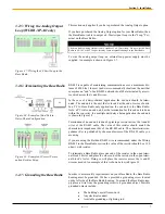
Once you have located these terminal blocks you can wire the Base Radio
accordingly. The best way to wire the Base Radio is to:
•
Remove both terminal blocks from the jacks on the Base
Radio
•
Insert the wire through the conduit hole on the bottom right
of the Base Radio
•
Secure the wire into the proper terminal blocks
•
Then plug the terminal blocks back into the proper jacks on
the Base Radio.
Figure 3.3: Terminal Block Labels
Caution
If the Base Radio is not energized for more than
30 minutes, the Field Units should also be turned
off to preserve battery life. Leaving the Field
Units on when the Base Radio is not energized or
out of range will cause the Field Units to transmit
very frequently and drastically reduces their bat-
tery life.
!
!
Summary of Contents for WI-BR-I-XP
Page 2: ......
Page 4: ......
Page 30: ...Accutech Wireless Base Radio User Manual 24 Rev 1 56 Base Radio Menu Map Appendix B...
Page 31: ......


