


Rev 1.56
17
Section 6: Configuring the Modbus Communications
6.3.1.2.1: Field Unit Device Type
Registers
The following are possible values for the Device Type holding registers.
Note that the register is a 32-bit floating point value for Field Units.
Value Device
Type
0 Acoustic Monitor Field Unit
1 RTD Field Unit
2 Pressure Field Unit
3 Dual 0-10V Input Field Unit
4 Dual 4-20mA Input Field Unit
5 Thermocouple Field Unit
6 Reserved
7 Level Sensor Field Unit
8 Split RTD Field Unit
9 Split Pressure Field Unit
10 Split Dual Thermocouple Field Unit
11 Differential Pressure Field Unit (100 IN. H20)
12 Split Differential Pressure Field Unit (100 IN. H20)
13 Differential Pressure Field Unit (300 IN. H20)
14 Split Differential Pressure Field Unit (300 IN. H20)
15 Differential Pressure Field Unit (25 PSID)
16 Split Differential Pressure Field Unit (25 PSID)
17 Differential Pressure Field Unit (100 PSID)
18 Split Differential Pressure Field Unit (100 PSID)
19 Differential Pressure Field Unit (300 PSID)
20 Split Differential Pressure Field Unit (300 PSID)
6.3.1.2.2: Field Unit Device Status
Registers
The following are the values for the Device Status holding registers.
These registers are bit field registers represented as a 32-bit floating point
value for Field Units.
Value
Field Unit Device Status
1 Field Unit Online
2 Low Battery Condition
4 Alarm Condition
8 Sensor Error Condition
16 Sensor Overrange Condition
32 System Error Condition
64 Switch Input 1 High
127 Switch Input 2 High
256 Sq. Root Funct. ON (DP Only)
Again, like Section 6.3.1.1.3, the status can be resolved by subtracting the
largest number listed above from the value received from the holding reg-
ister, and then subtracting the next highest and so on until the result is 0.
Each of the values used indicate the respective condition listed above.
E.g., holding register reads 12, then subtract 8 and get 4. Then subtract 4
from 4 and get 0. Thus we have a sensor error and alarm condition from
the list above.
Summary of Contents for WI-BR-I-XP
Page 2: ......
Page 4: ......
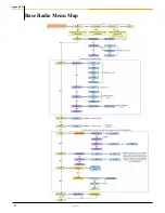
Page 30: ...Accutech Wireless Base Radio User Manual 24 Rev 1 56 Base Radio Menu Map Appendix B...
Page 31: ......


