background image


27 


30.  Sunlight high alarm 

31.  Sensor (CH1) Temperature high alarm 

32.  Sensor (CH1) Temperature low alarm 

33.  Sensor (CH1) Humidity high alarm 

34.  Sensor (CH1) Humidity low alarm 

35.  Sensor (CH1) Heat Index high alarm 

36.  Sensor (CH1) Heat Index low alarm 

37.  Sensor (CH1) Dew Point high alarm 

38.  Sensor (CH1) Dew Point low alarm 


Note: 

To prevent repetitive temperature alarming, there is a 0.5 °C tolerance band. For example, if you set 

the high alarm to 26.7 °C and silence the alarm, the alarm icon will continue to flash until the temperature falls 
below 26.2°C, at which point, the alarm will reset and must increase above 26.7 °C to activate again. 


Note: 

To prevent repetitive alarming of humidity, there is a 4% tolerance band in humidity alarm. For 

example, if you set the high alarm to 60% and silence the alarm, the alarm icon will continue to flash until the 
humidity falls below 56%, at which point, the alarm will reset and must increase above 60% to activate again. 


Alarm and Command Button Beeper ON/OFF Mode 

The beeper can be silenced for both alarms and button presses. 

In normal mode, press and hold the 

ALARM 

button for three seconds to toggle the beeper on or off 

(depending on the current setting). 

The 

BZON

 (beeper on) or 

BZOFF

 (beeper off) icon will appear in the time area for three seconds. press and 

hold the 

ALARM 

button again for three seconds to toggle the 

BZON

 or 

BZOFF

 command. 


Wi-Fi Connection Status 

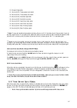
When the console successfully connects to your Wi-Fi router, the Wi-Fi signal icon 

 will appear on the 

LCD display (to the left of Indoor Temperature). If the Wi-Fi signal is not stable or the console is trying to 
connect to the router, the icon will flash. If the icon disappears, it means the console is not connected to the 
Wi-Fi router. 

Note: If you own a dual band router (2.4 GHz and 5.0 GHz), make sure you connect to the 2.4 GHz 

band, otherwise it will fail to connect the weather station to Wi-Fi. 


5.9. Time Server Sync Status 

After the console has connected to the internet, it will attempt to connect to the internet time server to obtain 
the time. 

Once the connection succeeds and the console’s time has updated, the SYNC icon 

 will 

appear on the LCD. The time will automatically synchronise to the internet each hour. 


Note: Time synchronisation method: Synchronised through internet UTC time server. 


Summary of Contents for DWS7100

Page 1: ...User Manual ACCUR8 DWS7100 Weather Station...

Page 2: ...o improve the design and specification of our products we reserve the right to change any detail given without prior notice Tempcon Instrumentation Ltd shall not be responsible for any liability of an...

Page 3: ...Display Console Operation 21 6 Registration with Weather Server Websites 28 7 Wi Fi Setup Connect your Device to the Console s Wi Fi 39 8 Upgrade firmware 45 9 Other Console Features 47 10 Specificati...

Page 4: ...the device and should be easily accessible as the mains cable plug is used to disconnect the device from the power supply Before starting up the device check the device the cables and the connections...

Page 5: ...s that comply with the technical information Use only the recommended batteries Always replace weak or empty batteries with a new complete set of batteries at full capacity Do not use batteries from d...

Page 6: ...DWS7100 weather station consists of the following parts as referenced in Figure 1 below QTY Item Image 1 Display console Frame dimensions L x H x W 215 x 22 x 158mm LCD dimensions L x W 170 x 125mm 1...

Page 7: ...Image 1 Mounting bracket back plate pole mount Dimensions 76 x 102 x 38mm 1 Mounting pole Dimensions 76 x 76 x 25mm 2 Pole mounting nuts M3 bolts 3 4 Pole mounting nuts M5 bolts 5 4 Tapping screws 1 U...

Page 8: ...Adjustable spanner Hammer and nail for hanging remote thermo hygrometer transmitter 3 3 Sensor Assembly Set Up Figure 2 shows the sensors included in the Integrated Outdoor Transmitter Figure 2 Inser...

Page 9: ...8 Figure 3 Remove the battery door by removing the set screw as shown in Figure 4 Figure 4 Insert 3 x AA batteries in the battery compartment as show in Figure 5...

Page 10: ...sors The solar panel does not charge the batteries so rechargeable batteries are not needed or recommended Note We recommend installing Lithium AA batteries for sensors The sensor LED indicator will l...

Page 11: ...door on the back of the sensor by removing the set screw as shown in Figure 7 Figure 7 1 BEFORE inserting the batteries locate the dip switches inside the battery compartment of the transmitter Figur...

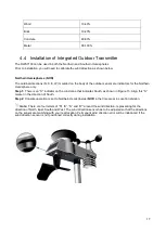
Page 12: ...2 3 4 DOWN DOWN DOWN Channel 1 DOWN DOWN UP Channel 2 DOWN UP DOWN Channel 3 DOWN UP UP Channel 4 UP DOWN DOWN Channel 5 UP DOWN UP Channel 6 UP UP DOWN Channel 7 UP UP UP Channel 8 DOWN F UP C Table...

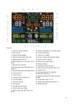
Page 13: ...t around the battery compartment is properly seated prior to closing the door Tighten the set screw 3 4 Display Console Display Console Layout The display console layout is shown in Figure 10 Note The...

Page 14: ...15 Moon phase 16 Sunlight units of measure 17 Sensor Heat index display 18 Sensor Heat index heat index dew point 19 Outdoor temperature and humidity display 20 Scroll mode indicator 21 Channel 1 8 in...

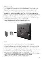
Page 15: ...perly Note The character contrast is best from a slightly elevated viewing angle Figure 11 Replace the battery door fold out the desk stand and place the console in the upright position The unit will...

Page 16: ...in the rain gauge Verify the rain reading on the display console is not reading 0 00 Each click represents 0 3mm of rainfall 2 Verify proper operation of the wind speed sensor Rotate the wind cups man...

Page 17: ...igh voltage lines Wireless signals will not penetrate metal buildings Most applications will only reach 30m due to building obstructions walls and interference 5 Radio interference from devices such a...

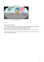
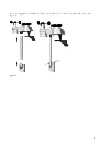
Page 18: ...ep 1 There is an S indicator on the wind vane that indicates South as shown in Figure 13 Align this S marker in the direction of South Step 2 Console operation is set to Northern Hemispheres NOR in th...

Page 19: ...sition when it comes to installing the Integrated outdoor transmitter Step 1 Install the Integrated outdoor transmitter and face the solar panel North Step 2 Set the Console operation to Southern Hemi...

Page 20: ...19 Fasten the integrated transmitter to mounting pole brackets with two 3 bolts and M3 nuts as shown in Figure 14 Figure 14...

Page 21: ...20 Attach the included mounting pole to your existing mounting pole with the four 5 bolts and M5 nuts assembly or fix on the wall with four tapping screws as shown in Figure 15 Figure 15...

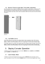
Page 22: ...ge is lower than 2 4V replace the batteries in the sensor with fresh batteries Never mix old and new batteries and never mix battery types such as alkaline and lithium together A low battery indicator...

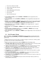
Page 23: ...st three seconds to enter the Set Mode The first setting will begin flashing You can press the SET MODE button again to skip any step as outlined below Note In the Set mode press the button or button...

Page 24: ...ing default partly cloudy Press the SET MODE button again to change the initial weather icon Press the button or button to select the initial weather icon of Sunny Cloudy Partly Cloudy or Rainy For de...

Page 25: ...ton for three seconds to clear all min values the pressure temperature and humidity minimum values The minimum values will now display the current values Press the CHANNEL button to switch the display...

Page 26: ...und audible To silence the beeper press any button Viewing the High and Low Alarms To view the current alarm settings press the ALARM button to enter the alarm mode HI AL 1 will be displayed in the da...

Page 27: ...The following is a list of the individual alarm parameters that are set in order 1 Alarm hour alarm 1 2 Alarm minute alarm 1 3 Alarm hour alarm 2 4 Alarm minute alarm 2 5 Outdoor temperature high alar...

Page 28: ...presses In normal mode press and hold the ALARM button for three seconds to toggle the beeper on or off depending on the current setting The BZON beeper on or BZOFF beeper off icon will appear in the...

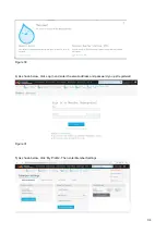
Page 29: ...ter a username email address and password This is your Login password for the website not your email account password So no private information will be exposed Sign Up 1 Click Sign up as below Figure...

Page 30: ...e 19 4 As shown below go to your email inbox and log in to the web address in the email you will have received Figure 20 5 As shown below click here to enter the homepage of the Weathercloud website F...

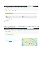
Page 31: ...registered to enter the Weathercloud website Figure 22 Add a weather station device it may take a few minutes Figure 23 1 After signing up you will be prompted to add a device Select Create device and...

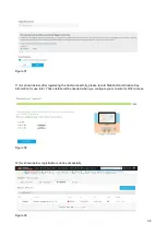
Page 32: ...ote You can select any Model number and Link type in the above boxes 2 As shown below click Get coordinates to identify your location of on the map then click Done to confirm Figure 25 3 As shown belo...

Page 33: ...and Key information for later use Figure 27 6 2 Register with Wunderground com Weather Underground Note The Weather Underground website is subject to change Visit https Wunderground com and select the...

Page 34: ...ername email address and a password this is your Login password for the website not your email password So no private information will be exposed Click Sign up for free Figure 29 3 As shown below regi...

Page 35: ...34 Figure 30 4 As shown below click Log in and enter the email address and password you just registered Figure 31 5 As shown below click My Profile Then enter Member Settings...

Page 36: ...Figure 32 6 As shown below click Update home location Figure 33 7 As shown below you will then be prompted to add a device Select Add New Device Figure 34 8 As shown below click Personal Weather Stati...

Page 37: ...36 Figure 35 9 As shown below select Address by inputting an address or select Manual to position your address automatically Then click Next...

Page 38: ...nformation about your device Complete the appropriate information then click I Accept and Next Boxes with red Required must be filled in Note You can select any Wi Fi weather station model in the Devi...

Page 39: ...ring the host successfully please record Station ID and Station Key information for use later These details will be needed when you configure your console for Wi Fi access Figure 38 12 As shown below...

Page 40: ...l mode the console icon infront of the Indoor Temperature will flash to signify that it has entered WAP wireless access point mode and is ready for you to enter Wi Fi settings You can use a desktop co...

Page 41: ...gure 41 your Wi Fi network name may be slightly different but will always begin with WeatherHome Figure 41 Example 3 Connect to the console Wi Fi server with an iPhone or iPad Choose the Settings icon...

Page 42: ...Fi server with an Android device From the Apps icon choose the Settings icon and Wi Fi Connect to the WeatherHome Wi Fi network as shown in Figure 43 your Wi Fi network name may be slightly different...

Page 43: ...168 5 1 Enter the following information into the web interface Figure 44 Make sure all of the information is entered prior to selecting Save If you choose not to upload to Wunderground com or upload...

Page 44: ...HI 9 YST Yukon Standard Yukon Territory 8 PST Pacific Standard Los Angeles CA USA 7 MST Mountain Standard Denver CO USA 6 CST Central Standard Chicago IL USA 5 EST Eastern Standard New York NY USA 4...

Page 45: ...of the information you entered is correct press save to confirm Figure 45 If it does not check your web interface information again Figure 45 Once the setup is completed disconnect your device from th...

Page 46: ...igure 47 Multiple Sensor Features Wunderground com does not support multiple sensor channels Note The current temperature and humidity data is the Integrated Outdoor Transmitter 7 2 View your data on...

Page 47: ...address into the browser s address bar http 192 168 5 1 upgrade html Figure 48 Once connection is successful it will jump to the Upload Setting screen automatically Figure 49 Press Select File button...

Page 48: ...f barometric pressure In general when the pressure increases the weather improves sunny to partly cloudy and when the pressure decreases the weather degrades cloudy to rain The weather forecast is an...

Page 49: ...is rising and the previous condition is rainy Rainy Pressure is falling and the previous condition is cloudy Moon Phase The following moon phases are displayed based on the calendar date Feels Like Te...

Page 50: ...C 80 F the heat index is displayed as shown in the National Weather Service Heat Index Table below When the temperature is between 4 4 C 40 F and 26 7 C 80 F the OUT temperature is displayed Feels Li...

Page 51: ...t experience frequent changes in air pressure require a higher setting compared to locations where the air pressure is typically stagnant 14 6 Restore Factory Default To restore the console to factory...

Page 52: ...life Typically at least 12 months for base station with excellent reception Intermittent reception may reduce the battery life Typically at least 12 months for Integrated Outdoor Transmitter use lithi...

Page 53: ...nths Unscrew the rain collector funnel by turning it 30 counter clockwise Gently remove the rain collector funnel Clean and remove any debris or insects Re install the collector funnel after it has be...

Page 54: ...ay is working and the transmitter light is flashing once per 60 seconds Install a fresh set of batteries in the remote thermo hygrometer For cold weather environments install lithium batteries Make su...

Page 55: ...tteries with a fresh set of batteries Wi Fi does not display on console Check your router for problems 1 Check Wi Fi symbol on the display If wireless connectivity is successful the Wi Fi icon will be...

Page 56: ...character a limitation of Wundeground com not the station Example worknet is not a valid password but worknet is valid 2 Confirm your station ID is correct 3 Make sure the date and time is correct on...

Page 57: ...r information on the proper disposal Do not dispose of electronic devices in the household rubbish As per Directive 2012 19 EC of the European Parliament on waste electrical and electronic equipment u...

Reviews: