Rev. 202206V1
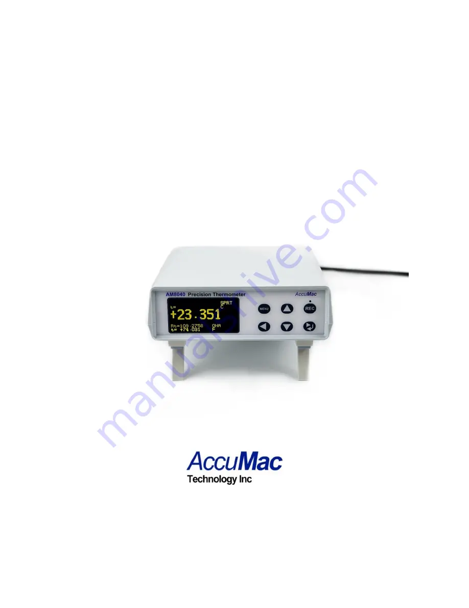
AM8040 Precision Thermometer
User’s Guide
Please download the latest version at www.accumac.com
Page 1: ...Rev 202206V1 AM8040 Precision Thermometer User s Guide Please download the latest version at www accumac com...
Page 2: ...C power 7 4 3 Instrument front panel display and touchpad 8 5 Instrument Calibration and Accuracy Adjustments 10 5 1 100 calibration 11 5 2 25 calibration 14 6 Selection of Sensors and Adjustment of P...
Page 3: ...be at the measurement left position Loss of calibration data will occur if the switch is at the calibration CAL position when the instrument is used in measurement application The instrument is calibr...
Page 4: ...the simple plug and record function Alternatively it can work with an optional wireless module to acquire and record data remotely through wireless With these flexible peripherals temperature data ca...
Page 5: ...esistance 2 7 OLED display Touchpad for function control Flexible sensor parameter adjustment and setting USB interface to computer for real time temperature capturing and data saving Wireless real ti...
Page 6: ...100 RTD PRT or SPRT Characterizations ITS 90 coefficients Callendar Van Dusen coefficients IEC 751 DIN 385 Sample Interval 1 second Display 2 7 inch OLED Display Units C F Excitation Current 1 mA reve...
Page 7: ...e Status Status Status Type Key Recording Start Stop Key Main Display Left Key Parameter Return Adjust Key Right Key Figure 1 Front Panel Rear Panel AC Power Inlet Switch Sensor terminals Flash Drive...
Page 8: ...4 1 Connecting the probe sensor The four wire sensor should be connected to the Sensor terminals at the rear panel Figure 3 shows how the four wire sensor should be connected It should be noted that...
Page 9: ...he LCD display functioning as a status indicator The status sign blinks when the device is powered on Line 1 is the instrument s interface status including USB flash drive wireless communication statu...
Page 10: ...can be scrolled to show different information The above example is page 1 The third page shows the resistance of the sensor The second page is the combination of page 1 and page 3 Users can scroll up...
Page 11: ...librated correctly Every AM8040 is calibrated before shipment Users can calibrate AM8040 using standard resistors with calibrated values A one year calibration interval is recommended Warning It is re...
Page 12: ...Calibration Configuration at Rear Panel 5 1 2 Turn on the power After initialization AM8040 shows the calibration main menu There are two calibration selections 100 Ohm CALIBRATION and 25 Ohm CALIBRAT...
Page 13: ...Resistor and Press Enter to indicate that a 100 resistor must be connected first Users can exit the calibration by pressing the MENU key to go back to the main menu CALIBRATION MENU 5 1 5 After the se...
Page 14: ...xit v Adj 100R Rs OHM 5 1 7 It is required to wait for 15 to 20 seconds before the data are stable The next step is to save the calibrated data to the instrument To save the data press the MENU key an...
Page 15: ...l is set to the CAL side right side as shown in Figure 4 Turn on the power 5 2 2 Choose 25 Ohm CALIBRATION under the main menu CALIBRATION MENU by pressing the or keys to move the cursor to the 25 Ohm...
Page 16: ...hen show 25 9977 Rt 25 0000 OHM Menu Exit Enter Yes 25R Rs OHM 25 Ohm CALIBRATION The value on the third line is the parameter to be adjusted and this value must match the standard resistance of the 2...
Page 17: ...ption to save 5 2 7 To save this calibration result press and hold the key and then press the key at the same time This will save the calibration data to the instrument and the program will go back to...
Page 18: ...named as IPRT and SPRT If the probe is an industrial or precision platinum resistance thermometer probe with a temperature coefficient of 0 00385 C AM8040 will categorize the probe as IPRT AM8040 will...
Page 19: ...external flash drive iii Wireless Setting Users can select wireless communication settings optional 2 Press the or keys to move the highlighter line with to Sensor Setting Press the key to enter the S...
Page 20: ...hese parameter definitions can be found from ITS 90 As an example calibration agencies provide the following parameters after an SPRT is calibrated Rtp probe s resistance at the triple point of water...
Page 21: ...ient when the temperature is lower than 0 C 6 MENU and keys can be used together to adjust these parameters The parameters can also be saved into the instrument The following example is the procedure...
Page 22: ...ent procedure Continuing from Step 4 press the or keys to move the cursor to SET a4 and then press the key to go to the a4 adjustment program as shown below SPRT SETTING SET a4 0 MENU Exit ENTER Yes a...
Page 23: ...adjustment users can choose to save or quit the a4 adjustment by pressing the MENU key The a4 line will flash to remind the user that a change has been made To save the changes press the key if not p...
Page 24: ...ee software for this feature is included with the AM8040 W The following components are need for this feature AM8040 precision thermometer with embedded wireless function A wireless transceiver A USB...
Page 25: ...eless transceiver to the computer with a USB cable Place it at a high spot for best performance The system setup is shown in Figure 5 4 After connecting the wireless transceiver to the computer the us...
Page 26: ...ecision thermometer The data after RSSI is the wireless signal strength which should be a two digit number after clicking on Start The RSSI should be greater than 99dBm Otherwise the wireless signal i...
Page 27: ...data acquisition can be restarted by clicking on Start if Stop has been pressed before 10 CoolDragon_Air_Reader can also save the captured data to a file Air_data txt The data sampling rate can be adj...
Page 28: ...the modification If the captured data need to be saved users can start the saving by clicking on Start and then clicking on the REC button The captured temperature can be saved into Air_data txt and...
Page 29: ...g time which should be same as the computer time The second column lists the temperature Each time Stop is pressed the data saving will be halted and end recording will be added to the file If users w...
Page 30: ...briefly show Device Detected D p to indicate that the flash drive has been detected and then the upper left corner of the display should display UDr to remind users that a flash drive is connected and...
Page 31: ...pture t C Time 267 178 0 24 267 178 1 21 267 178 2 17 267 178 3 14 267 178 4 10 end 7 The above operations can be repeated to do multiple data saving sessions 8 The temperature data file MYDATA txt in...
Page 32: ...Setting b Press the key or the key to move the cursor line with the sign to U Drive Setting then press the key to go to the Record Cycle adjustment program as shown below N represents how often the te...
Page 33: ...he file every 9x0 97 seconds To save this value do the following two key operation press and hold the key and then press the key if users DON T want to save just press the MENU key to exit Note this o...
Page 34: ...to the USB USB B type interface at the rear panel of AM8040 and to a computer Figure6 AM8040 USB Temperature Data Acquisition System 2 The first time that an AM8040 is connected to a computer the comp...
Page 35: ...a file named U_data txt The default sampling period is 1 second Users can also adjust the sampling period for their requirements The instruction is as follows a Find the Every x Sec section of the Dat...
Page 36: ...will be saved to U_data txt file and Recording should be shown if users want to stop the data saving just click on END or Stop and the temperature data saving will be stopped The following figure sho...
Page 37: ...structions below AM8040 precision thermometer and wireless transceiver are designed with a USB interface The installation of a USB driver is required the first time these instruments are connected to...
Page 38: ...Thermometer User s Guide Rev 202206V1 37 40 2 Put the attached CD into the CD ROM drive and then select No not this time and click on Next 3 Select Install from a list or specific location Advanced an...
Page 39: ...rmometer User s Guide Rev 202206V1 38 40 4 Search the CD drive Drive E in this example by using Browse as in the above figure then click Next 5 Select Continue Anyway the computer will search for anot...
Page 40: ...Use Browse to search for and select FTD2XX sys then click on OK After the installation the computer should show 7 Select Finish to end the installation 8 The computer should show You new hardware is r...
Page 41: ...erms the warranty terms in the separate agreement shall control Each product from AccuMac Technology is warranted to be free from defects in material and workmanship under normal use and service The w...