background image

12

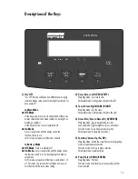
Scale connected to AC power:

On/Off Switch: 

On: Scale is operational & display shows function or mode
that is in use
Off: Depends on menu setting (“4. Standby option.”),
scale is completely off (no display and no internal circuitry)
or in standby (no display and internal circuitry working).

Back Light:

Depends on menu setting (“2. Backlight”). Backlight is
on/off.

Auto Power Off: 

Not active.

Scale running on battery power:

On/Off Switch: 

On: Scale is operational and the display shows the function
or mode that is in use
Off: Completely off (no display and no internal circuitry)

Back Light:

Depends on menu setting (“2. Backlight”). Backlight is
on/off. Backlight goes off after 15 seconds if no operation
is done (no key pressrd/no weighing). Backlight comes
back on whenever a key (except on/off) is pressed or
when a load is placed on the scale.

Auto Power Off:

Depends on menu setting (“3. Auto power off”); system
power shuts down. Time limit options for auto power in
setup menu are 5, 10 or 15 minutes, or can be disabled.

Power Management Option

Summary of Contents for ECL15

Page 1: ...98648 017 24 Operating Instructions Acculab Exceleron Series ECL Models Tare Gross Net Fn Function Gross Net Tare Zero 0 Print Enter EXCELERON...

Page 2: ...rge backlit display segments Large keys with positive click action Fast response times Automatic initialization when you switch on the Exceleron Optional Control through an external computer 2 Content...

Page 3: ...rking on the instrument when it is switched on can be dangerous to life Disconnect the instrument from the supply voltage When removing covers of parts by means of tools live parts or terminals may be...

Page 4: ...rm such work are allowed to use suction lifting equipment Always make sure the scale is disconnected from AC power before performing any installation cleaning maintenance or repair work Check the pin...

Page 5: ...perating instructions Installation Instructions The Acculab Exceleron scales are designed to provide reliable weighing results under normal ambient conditions When choosing a location to set up your s...

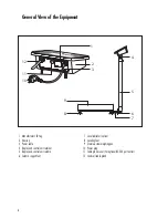
Page 6: ...iner 5 Display and control unit column 6 Column support foot 7 Level indicator option 8 Leveling feet 9 Stainless steel weighing pan 10 Power plug 11 Cable gland cover for optional RS 232 port outlet...

Page 7: ...f activate battery mode before you connect or disconnect a peripheral device printer or PC to or from the interface port Warm up Time To deliver exact results the scale must warm up for at least 30 mi...

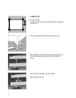
Page 8: ...indicator Check to ensure that all leveling feet rest securely on the work surface Under the metal frame structure there are four safety overload protection pins The transportation protection nut is p...

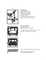
Page 9: ...the screw on the display and control unit bracket Battery Powered Operation To activate battery operation Open the battery cover at the back of the Indicator If you purchased the system with the dry...

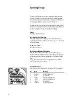
Page 10: ...angle b this indicates that the scale is performing a function busy symbol a plus or minus sign or this applies to the value displayed The Measured Value Shows the measured value Basic Unit and Additi...

Page 11: ...th a jumper wire Operating Limits Never exceed the maximum capacity of the scale The maximum loading capacities of the scale in this series are listed in the table below and depend on the position of...

Page 12: ...On Off Switch On Scale is operational and the display shows the function or mode that is in use Off Completely off no display and no internal circuitry Back Light Depends on menu setting 2 Backlight B...

Page 13: ...the system shuts off when not in use in accordance with the setup menu setting 2 Zero Arrow Left ZERO LEFT Weighing mode Set scale to zero Parameter mode Shift position of digit to the left 3 Tare Arr...

Page 14: ...OFF 3 While all the segments are displayed ZERO LEFT 2 sec Navigation in the Setup Menu Key Function PRINT ENTER Menu item confirm setting Fn UP Menu item Scroll up Digit input Increment G N DOWN Men...

Page 15: ...No options 3 2 5 Min 3 4 15 Min 3 3 10 Min 5 1 Very stable conditions 5 2 Stable conditions 5 3 Unstable conditions 5 4 Very unstable conditions 6 1 Decimal point 6 1 1 0 6 3 Step width 6 3 1 1 6 1 5...

Page 16: ...ay tared e Select reference sample quantity Fn UP or G N DOWN repeatedly 5 10 20 50 or 100 and put the reference on the scale quantity flashes f Press PRINT ENTER Now O flashes PRINT ENTER Automatic o...

Page 17: ...shes Fn UP or G N DOWN and or ZERO LEFT or TARE RIGHT e Press PRINT ENTER to confirm and save PRINT ENTER f Set upper limit HI flashes Fn UP or G N DOWN and or and then press PRINT ENTER ZERO LEFT or...

Page 18: ...Units Fn UP or G N DOWN Repeatedly c Select weight unit 1 Fn UP or G N DOWN d Confirm weight unit 1 PRINT ENTER e Select weight unit 2 Fn UP or G N DOWN f Confirm weight unit2 PRINT ENTER g Place sam...

Page 19: ...DOWN Repeatedly e Confirm start calibration PRINT ENTER After the zero point is stored the required calibration weight is displayed f Place the required weight on the scale g If the weight is applied...

Page 20: ...d within the defined time PRINT ENTER limit and tolerance the OK symbol is displayed Press PRINT ENTER to confirm and save calibration To exit linearization press ZERO LEFT 2 sec h The next linearizat...

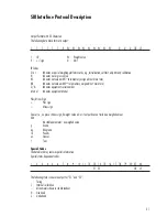
Page 21: ...N Indicates equipment serial number M o d e l Indicates equipment Model Plus Minus Sign Plus sign Minus sign Space i e no plus or minus sign if weight value is 0 or if output does not include a weighe...

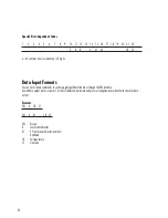
Page 22: ...ou can enter certain commands to control weighing platform functions through the SBI interface As with data output data is input as 7 bit ASCII characters hardware and protocol configuration are ident...

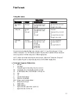
Page 23: ...e combination ESC V CR LF Zero the weighing platform ESC U CR LF Tare the weighing platform ESC S CR LF Reset ESC O CR LF Lock keyboard ESC R CR LF Unlock keyboard ESC x 1 _ CR LF Output model name ES...

Page 24: ...r or different peripheral device to the scale using RS 232 cable length up to 15 m RS 232 Interface Diagram 24 Tare Gross Net Fn Function Gross Net Tare Zero 0 Print Enter EXCELERON TXD RXD 1 3 GND GN...

Page 25: ...Reference weight counting application Pcs Number of units on the pan g Weight in Grams kg Weight in kilograms Appears if the value is greater than or equal to zero Appears if the value is less than ze...

Page 26: ...gle key is pressed G 300 g Ex 2 After unit is toggled to kilograms G 0 300 kg 2 Block printing mode 2 1 Normal weighing Ex 1 If tare is zero G 200 g Ex 2 If tare is not zero G 100 g T 50 g N 50 g 2 2...

Page 27: ...00 g HL 400 g 2 4 Unit toggling Ex 1 Before toggle key is pressed G 300 g T 200 g N 100 g Ex 2 After unit is toggled to kilograms G 0 300 kg T 0 200 kg N 0 100 kg 3 Continuous printing mode 3 1 Normal...

Page 28: ...ale setting not allowed to the customer APPErr Weight is too high or there is no sample Increase the weight on the scale on the scale with application in use PrtErr Data interface for printing is bloc...

Page 29: ...ces of corrosive substances from the weighing platform on a regular basis Safety Inspection If there is any indication that safe operation of the scale with the AC is no longer warranted Turn off the...

Page 30: ...dry battery Load plate Platform code DC ED FE GF GG IG stainless steel LL NL NN RN RR WR painted steel Housing material ABS Column Length 350 mm 500 mm 750 mm Measurement category Category 1 maximum 8...

Page 31: ...must check and if necessary correct these modifications On request Acculab will provide information on the minimum operating specifications in accordance with the Standards listed above for defined i...

Page 32: ...rmission of Acculab The status of the information specifications and illustrations in this manual is indicated by the date given below Acculab reserves the right to make changes to the technology feat...

Reviews: