


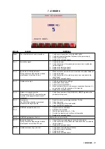

START
STOP
7
6
5
4
3
2
1
M
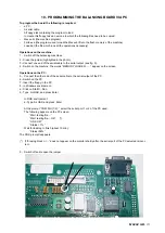
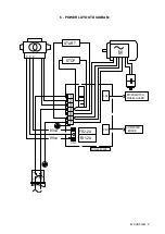
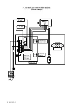
POWER BOARD
FS1-2A
FS2-2A
MICROSWITCH
WHEEL GUARD
CN2
COMPUTER
BOARD
CN1
1
2
1A
2A
M 0496 GB
-
9
8 - HOW TO CHECK FUNCTIONING AND ACCURACY
Further to some notices informing us of defects and unaccuracies not clearly traceable, we are explaining hereunder
the procedure how to check functioning and accuracy to help us to detect problems.
FIRST CHECKS
Accurate wiping of adapter and cones
Spring cover sliding
Shaft end blocking
TEST OF PROPER ENCODER FUNCTIONING
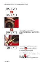
1. Cleaning the encoder
Remove the snap cover on the chuck side.
Insert a tool until it touches the phase disc (use a soft brush to prevent damaging the decals).
Slowly turn the wheel by hand several times to allow the tool to remove any residual dust.
Never force the tool on the phase generator.
After cleaning, close the snap cover.
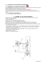
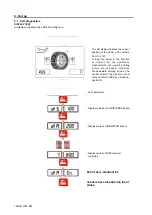
2. Positioning the encoder card
It is recommended to position the encoder card in the following cases:
- If replacing the encoder card;
- If replacing, cleaning or generally working on the encoder decals;
- In the event of repeated errors 1,2,11,12,13,14,15,16,17,18 detected by the wheel balancer during the unbalance
measurement phase;
- In the event of unjustified unbalance oscillation.
Before running the encoder test, ALWAYS check that there is a maximum distance of 1 mm between the decal and
the encoder card and that the retaining nuts of the encoder card are adequately tightened.
Use a wheel of average dimensions.
Press:
[MENU]
[
]
The word [Setup] appears
[ENTER]
The word [Diagn.] appears
[MENU]+[STOP]+[MENU]
Press in sequence in maximum 5 sec.
[
]
The word [Enc.] appears
[ENTER]
The word [Start] appears
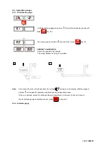
[START] The test cycle is run after which the following results must be obtained for the encoder to function properly:
[ 32] [ 32]
Number of encoder pulses A/B
[Min.] [0.15]
The number displayed must be in a range of 0.12%0.25.
[xxx]
[xxx]
The number shown on the left-hand display must be higher by as much as possi
ble than the right-hand number and both values must be as far as possible away
from 0.
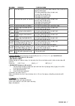
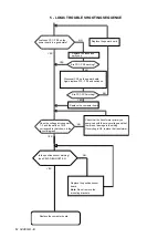
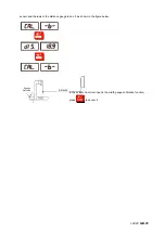
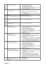
MEANING OF ENCODER TEST ERRORS
ERR. 1
No reset signal.
1. Check the connection cable between the encoder card and
the CPU board.
2. Check positioning of the encoder card.
3. Clean the encoder decal.
4. Replace the encoder card
5. Replace the CPU board
ERR. 2
Encoder test speed not reached.
1. Check positioning of the encoder card.
2. Clean the encoder decal.
3. Replace the encoder card
4. Replace the CPU board
ERR. 4
Incorrect direction of rotation.
1. Check the encoder card connection cable.
ERR. 33 Rising edge fault detected for ENCA. 1. Check positioning of the encoder card.
2. Clean the encoder decal.
ERR. 34 Falling edge fault detected for
ENCB.
1. Check positioning of the encoder card.
2. Clean the encoder decal.
ERR. 35 Falling edge fault detected for
ENCA.
1. Check positioning of the encoder card.
2. Clean the encoder decal.
Summary of Contents for 1250
Page 1: ...SERVICE MANUAL MODELS 1250 1450 1550 1650 1850...
Page 2: ......
Page 3: ...Model 1250 Wheel Balancer...
Page 5: ...M 0495 2 GB...
Page 9: ...M 0495 6 3 GB 5 POWER SUPPLY LAYOUT DIAGRAM 230 V connection...
Page 10: ...M 0495 7 4 GB 6 REPLACING THE POWER BOARD check voltage...
Page 14: ......
Page 15: ...Model 1450 Wheel Balancer...
Page 17: ...M 0492 2 GB...
Page 30: ......
Page 31: ...Model 1550 Wheel Balancer...
Page 33: ...M 0493 2 GB...
Page 40: ...M 0493 9 5 GB 6 POWER SUPPLY LAYOUT DIAGRAM...
Page 41: ...M 0493 10 6 GB 7 TO REPLACE POWER BOARD...
Page 46: ......
Page 47: ...Model 1650 Vibration Control Diagnostic System...
Page 49: ...M 0494 2 GB...
Page 55: ...M 0494 8 5 GB 7 POWER SUPPLY LAYOUT DIAGRAM...
Page 56: ...M 0494 9 6 GB 8 TO REPLACE POWER BOARD...
Page 62: ......
Page 63: ...Model 1850 Wheel Balancer...
Page 65: ...M 0496 GB 2...
Page 76: ...SERVICE MANUAL MODELS 1250 1450 1550 1650 1850...


