Installa
ti
on instruc
ti
ons for the OPEN Classic out of pool automa
ti
c safety cover - 4/20
4
1. Preparing the pool
1.1
Electric
connec
ti
ons and cable passages
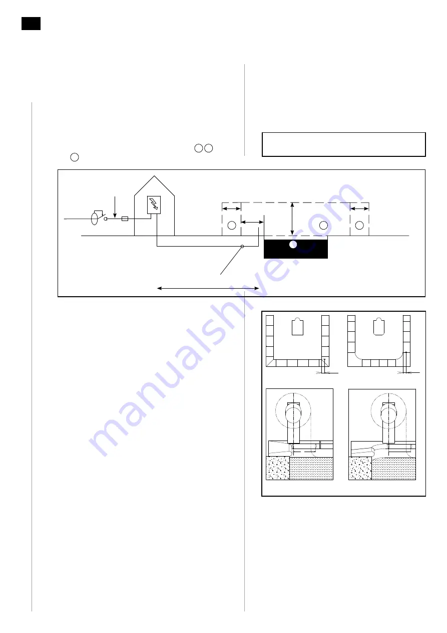
1.1.1 Electric box power supply
Fig. 1
Prepare a 230 V power supply using an R2V3G2.5
mm² (or Ro2V 3G2.5 mm²) cable for the electric box,
which must be installed outside the volumes,
1
0
and
2
and in a dry place (technical room).
1.1.2 Electrical
protec
ti
on
The power supply must be protected by a circuit
breaker or a 10 A fuse holder and a 30 mA ground
fault circuit breaker.
1.1.3 Sheaths
Prepare a connec
ti
on protected by a sheath for the
24 V DC power supply between the box and the
roller using 2 x 4 mm² if the cable is less than 15 m
long and using 2 x 6 mm² if the cable is between 15
m and 30 m long.
1.1.4 Water treatment communica
ti
on op
ti
on
Plan a connection between the box and the
roller using 2 x 1.5 mm² if you are installing the
"communication with water treatment device
op
ti
on" box.
1.1.5 Cable
passages
Separate cables carrying di
ff
erent voltages (24 V and
220 V) by passing them through di
ff
erent sheaths
which are spaced in compliance with NF C 15-100.
1.1.6 Cable
exit
Fig. 2
Exit these cables 10 cm from the edge of the pool
in the alignment of the rear copings of the pool in
the case of 90° corner copings. If necessary advance
them by the distance of the radius of the curved
part of the pool's angle.
Consult the current electric standards and
especially the NF C15-100 standard.
Fig. 2
10cm
10cm
x
x
10 cm
10 cm
X
X
Fig. 1
230 V 50 Hz
30 mA
3 x 2.5mm²
10 A
0 m < D < 15 m
→
2 x 4 mm
2
15 m < D < 30 m
→
2 x 6 mm
2
D
2 m
2.5 m
1.5 m
1.5 m
0
1
2
2


