


MC80F0304/08/16
November 4, 2011 Ver 2.12
65
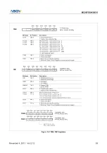
Figure 13-8 Count Operation of Timer / Event counter
13.2 16-bit Timer / Counter Mode
The Timer register is being run with all 16 bits. A 16-bit timer/
counter register T0, T1 are incremented from 0000
H
until it
matches TDR0, TDR1 and then resets to 0000
H
. The match out-
put generates Timer 0 interrupt.
The clock source of the Timer 0 is selected either internal or ex-
ternal clock by bit T0CK[2:0]. In 16-bit mode, the bits
T1CK[1:0] and 16BIT of TM1 should be set to "1" respectively
as shown in Figure 13-9 .
Likewise, A 16-bit timer/counter register T2, T3 are incremented
from 0000
H
until it matches TDR2, TDR3 and then resets to
0000
H
. The match output generates Timer 2 interrupt.
The clock source of the Timer 2 is selected either internal or ex-
ternal clock by bit T2CK[2:0]. In 16-bit mode, the bits
T3CK[1:0] and 16BIT of TM3 should be set to "1" respectively
as shown in Figure 13-10 .
Even if the Timer 0 (including Timer 1) is used as a 16-bit timer,
the Timer 2 and Timer 3 can still be used as either two 8-bit timer
or one 16-bit timer by setting the TM3. Reversely, even if the
Timer 2 (including Timer 3) is used as a 16-bit timer, the Timer
0 and Timer 1 can still be used as 8-bit timer independently.
Timer 1 (T1IF)
Interrupt
TDR1
TIME
Occur interrupt
Occur interrupt
stop
clear & start
disable
enable
Start & Stop
T1ST
T1CN
Control count
up
-c
oun
t
~~
~~
T1ST = 0
T1ST = 1
T1CN = 0
T1CN = 1