


MC80F0304/08/16
November 4, 2011 Ver 2.12
13
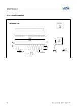
7.50
1
BSC
10.30 BSC
0.31
2
1.27 BSC
0.40
28 SOP
17.90
1
BSC
0.51
2
1.27
unit: millimetres
MAX
MIN
0.3
3
4
0.20
4
2.0
5 MIN
2.65 MAX
0.30 MAX
3
1.40 REF
0.25 B
S
C
SEATING PLANE
GAUGE PLANE
5 ~ 15°
5 ~ 15°
0 ~ 8°
1. 17.90 dimension does not include mold FLASH, protrusions or gate burrs.
2. This dimensions apply to the flat section of the lead between 0.10 to 0.25 mm from the lead tip.
3. This is defined as the vertical distance from the seating plane to the lowers point on the package body
4. This dimensions apply to the flat section of the lead between 0.10 to 0.25 mm from the lead tip.
Mold FLASH, protrusions or gate burrs shall not exceed 0.15mm per end.
7.50 dimension does not include interlead FLASH or protrusion.
Interlead FLASH or protrusion shall not exceed 0.25mm per side.
The package top may be smaller than the package bottom.
17.90 and 7.50 dimensions are determined at the outermost extremes of the plastic body exclusive of mold FLASH.
Tie bar burrs, gate burrs and interlead FLASH, but including any mismatch between the top and bottom of the plastic body.
Dimension does not include dambar protrusion.
Allowable dambar protrusion shall be 0.10 mm total in excess of the dimension maximum material condition.
The dambar may not be located on the lower radius of the foot.
excluding the thermal enhancemet on cavity down package configurations.