


Installing the Motherboard
User’s Manual
2-15
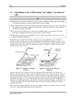
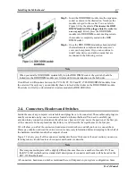
Figure 2-8. Ultra DMA 66
Ribbon Cable Outline
Note
!
The Master or Slave status of the hard disk drive is set on the hard disk itself. Please refer to the
hard disk drive user’s manual.
!
To connect Ultra DMA 100 & Ultra DMA 133 devices on IDE1 to IDE4, an Ultra DMA 66 cable
is required.
!
A red mark on a wire typically designates the location of pin 1. You need to align the wire pin 1 to
the IDE connector pin 1, before inserting the wire connector into the IDE connector.
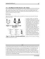
(12). D14, D16 and D17 LEDs Indicator: Status LEDs indicators
There are three indicators on the motherboard.
D14 is a standby power indicator. When the +5VSB
supplies power to the motherboard, this LED
indicator will light up.
D16 is a power on indicator. When the power button
is pressed, this LED indicator will light up.
D17 is a reset indicator. When you press the reset
button, this LED indicator will light up. If you
release the reset button, this indicator will turn off.
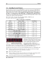
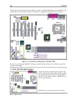
Figure 2-9. KX7-333/KX7-333R back panel connectors
Figure 2-9 shows the KX7-333/KX7-333R back panel connectors, these connectors are for connection to
outside devices to the motherboard. We will describe which devices will attach to these connectors below.
Summary of Contents for KX7-333
Page 2: ......
Page 26: ...Chapter 2 KX7 333 KX7 333R 2 18 ...
Page 68: ...4 6 Chapter 4 KX7 333 KX7 333R ...
Page 76: ...6 4 Chapter 6 KX7 333 KX7 333R ...
Page 82: ...A 6 Appendix A KX7 333 KX7 333R ...
Page 88: ...B 6 Appendix B KX7 333 KX7 333R ...
Page 96: ...D 4 Appendix D KX7 333 KX7 333R Note Items between the are absolutely necessary ...
Page 100: ...D 8 Appendix D KX7 333 KX7 333R ...
Page 104: ...E 4 Appendix E KX7 333 KX7 333R ...