background image

Knowing Your Motherboard 

2-9 

2.2.7. 

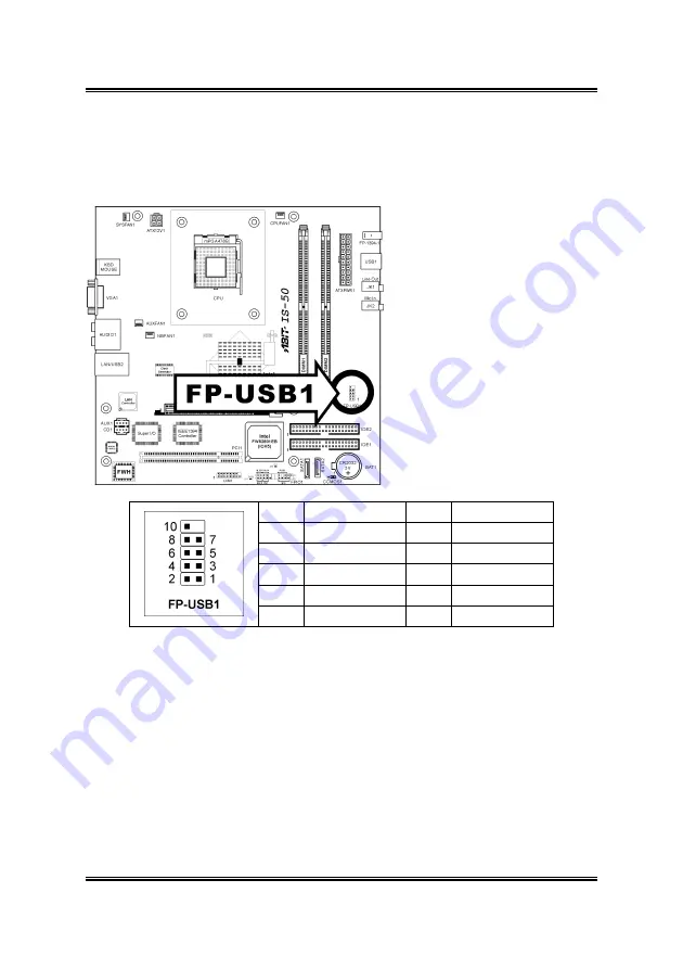
Additional USB Port Connection Header 

This header provides 2 additional USB 2.0 ports connection through an USB cable 
designed for USB 2.0 specifications. 


Pin

Pin Assignment

Pin

Pin Assignment

1 VCC 2 VCC 

3 Data0 

- 4 Data1 

5 Data0 

+ 6 Data1 

7 Ground 8 Ground 


9  NC 10 NC 

User’s Manual 

Summary of Contents for DigiDice AB-2003

Page 1: ...AB 2003 DigiDice Socket 478 Mini PC System User s Manual 4200 0382 24 Rev 1 01 ...

Page 2: ...hall the manufacturer be liable for direct indirect special incidental or consequential damages arising from any defect or error in this manual or product Product names appearing in this manual are for identification purpose only and trademarks and product names or brand names appearing in this document are property of their respective owners This document contains materials protected under Intern...

Page 3: ...e for a long time disconnect the equipment from mains to avoid being damaged by transient voltage 10 Never pour any liquid into opening this could cause fire or electrical shock 11 If one of the following situations arises get the equipment checked by service personnel a b c d e f The power cord or plug is damaged Liquid has penetrated into the equipment The equipment has been exposed to moisture ...

Page 4: ...AB 2003 DigiDice ...

Page 5: ...iew Operation 1 15 Chapter 2 Knowing Your Motherboard 2 1 2 1 Layout Diagram 2 1 2 2 Connectors Headers and Switches 2 2 2 2 1 ATX Power Input Connectors 2 2 2 2 2 FAN Connectors 2 3 2 2 3 CMOS Memory Clearing Header 2 4 2 2 4 Accelerated Graphics Port Slot 2 5 2 2 5 PCI Slot 2 6 2 2 6 Front Panel Switches Indicators Connection Headers 2 7 2 2 7 Additional USB Port Connection Header 2 9 2 2 8 LCM1...

Page 6: ...16 3 9 Install the Essential Oil Tank 3 19 Chapter 4 BIOS Setup 4 1 4 1 SoftMenu Setup 4 2 4 2 Standard CMOS Features 4 4 4 3 Advanced BIOS Features 4 7 4 4 Advanced Chipset Features 4 10 4 5 Integrated Peripherals 4 12 4 6 Power Management Setup 4 18 4 7 PnP PCI Configurations 4 20 4 8 PC Health Status 4 22 4 9 Load Fail Safe Defaults 4 24 4 10 Load Optimized Defaults 4 24 4 11 Set Supervisor Pas...

Page 7: ... The System 6 1 6 2 Easy OC Over Clocking Setting 6 2 6 3 Powering On The System 6 4 6 4 Hot Key Controlling 6 5 6 5 ABIT EQ and ABIT Manager 6 7 6 6 Memory Card Reading 6 11 6 7 Powering Off The System 6 12 Appendix A How to Get Technical Support A 1 User s Manual ...

Page 8: ...AB 2003 DigiDice ...

Page 9: ...ious room allows dual optical drives installation A tiny but complete CD disk copy station is realized at once Four Hot Keys Four hot keys in the front panel allow DVD VCD video play back CD MP3 audio play back photo viewing and CD copying by just one click AGP PCI Slot A system upgrade is easy to reach through additional AGP and PCI slot You can upgrade to a powerful VGA card or add on a PCI TV T...

Page 10: ...ng ABIT EQ System status can be monitored both through the LCD screen on front panel and the ABIT EQ software based application Remote Control A handy remote controller is also bundled in the package You can control and launch programs from distance 1 3 Installation Notice Compatible with Windows XP operation system only Must be applied together with ABIT Manager Must use in collocation with the a...

Page 11: ... 400 memory module up to 2GB Expansion slot 1x AGP slot two standard slot space for ABIT OTES AGP card 1x PCI slot IDE 2x ATA100 channels and 2x Serial ATA channels LAN 10 100Mbit LAN Audio 5 1 channel AC97 CODEC ABIT Engineered ABIT SoftMenu Technology ABIT Manager utility Hardware Monitoring Including Fan speed Voltages CPU and System Temperature Front Panel I O 1x IEEE 1394 connector 2x USB 2 0...

Page 12: ...nectors 1x RJ 45 LAN Connector Chassis Material Aluminum Bezel Color Silver Bundle Software InterVideo WinDVD InterVideo WinRip with MP3 encoder Dimension 307 x 215 x 255mm W x H x D with foot stand Drive Bays 2x 5 25 for optical devices 2x 3 5 for HDD Power Supply AC 100V 240V 50 60Hz input Maximum 200W output with PFC function Specifications and information contained herein are subject to change...

Page 13: ...klist Item Photo Quantity ATA 100 IDE Cable 1 ATA 33 IDE Cable 1 CPU Thermal Module 1 Driver Utility CD 1 Fan Duct 1 Power Cord Types differ depending on version 1 System Fan 1 User s Manual 1 Quick Installation Guide 1 User s Manual ...

Page 14: ...1 Carrying Bag bonus parts for deluxe version 1 Essential Oil bonus parts for deluxe version 1 Essential Oil Tank bonus parts for deluxe version 1 Remote Controller bonus parts for deluxe version 1 AB 2003 DigiDice ...

Page 15: ... Front Panel 1 Hot Keys 2 LCD Screen 3 IR Receiver Sensor 4 Card Reader Slot 5 5 25 Empty Tray For Optical Drive 6 Knob Controller 7 Microphone Jack 8 Headphone Jack 9 USB 2 0 Connector 10 IEEE 1394 Connector User s Manual ...

Page 16: ...wer Cord Connector 2 PS 2 Keyboard Connector 3 PS 2 Mouse Connector 4 VGA Out Connector 5 S PDIF Out Connector 6 5 1 Audio Connector 7 USB 2 0 Connector 8 LAN Connector 9 I O Shield for AGP Slot 10 I O Shield for PCI Slot AB 2003 DigiDice ...

Page 17: ...tput level Video Control Toggles the video playing program WinDVD Audio Control Toggles the audio playing program WinRip Photo Control Toggles the photo viewing program Windows XP Photo Browser Copy Control Toggles the CD copy program DigiBurner This function only works in the collocation of two optical disks one CD DVD ROM and one CD R CD RW Infrared Receiver Sensor Infrared receiver sensor for r...

Page 18: ...e will be ejected through this cover plate after pressing the eject button Eject Button Press this button to eject the optical drive You may have do a little adjusting if the disk plate of your optical drive cannot be ejected by pressing this button Slide the pointer on the adjusting rod behind this button so as to make it touches the eject button on optical drive AB 2003 DigiDice ...

Page 19: ...Introduction 1 11 1 10 LCD Screen Video Playing Temperature Audio Playing Fan Running Photo Viewing Disk Over load Copying Mode Network Connecting Volume Level System Suspend Alarm Alert User s Manual ...

Page 20: ... WinDVD WinRip and Photo Review from distance This easy control grants you an easy to reach AV entertainment This remote controller is powered by two AAA size batteries Point the infrared transmitter of the remote controller to the infrared receiver sensor on the front panel when accessing a remote command AB 2003 DigiDice ...

Page 21: ...nu Screen Full Screen Windows Audio Language Selection Subtitle Enter the subtitle Viewangle Adjust the viewing angle Playlist View the play list Volume Increase Volume Decrease Escape Step Forward Move one step forward Menu Enter the menu screen Up Down Left Right Arrow and Enter button Fast Backward Play Pause Fast Forward Last Chapter Stop Next Chapter User s Manual ...

Page 22: ...ylist View the play list Volume Increase Volume Decrease Escape Up Down Left Right Arrow and Enter button Record Shuffle Random play Play Pause Repeat Last Track Stop Next Track Jukebox DSP Enter digital signal processing menu Gallery Select All Select all tracks Audio CD Select audio CD AB 2003 DigiDice ...

Page 23: ...to Review Operation Power On Off Up Down Left Right Arrow and Enter button Launch Photo Review Last Page Start Pause Automatic Viewing Next Page Rotate Left Stop Automatic Viewing Rotate Right Zoom In Zoom Out Print User s Manual ...

Page 24: ...1 16 Chapter 1 1 16 Chapter 1 AB 2003 DigiDice AB 2003 DigiDice ...

Page 25: ...Knowing Your Motherboard 2 1 Chapter 2 Knowing Your Motherboard 2 1 Layout Diagram User s Manual ...

Page 26: ...he AC power cord before adding or removing any peripheral or component Failing to so may cause severe damage to your motherboard and or peripherals Plug in the AC power cord only after you have carefully checked everything 2 2 1 ATX Power Input Connectors Connects to ATX power supply AB 2003 DigiDice ...

Page 27: ...in your system The CPU must be kept cool by using a powerful fan with heatsink The system is capable of monitoring the speed of the CPU fan CPUFAN1 CPU Fan SYSFAN1 System Fan AUXFAN1 Auxiliary Fan NBFAN1 N B Chipset Fan WARNING These fan connectors are not jumpers DO NOT place jumper caps on these connectors User s Manual ...

Page 28: ...r the CMOS memory Pin 1 2 shorted default Normal operation Pin 2 3 shorted Clear CMOS memory ATTENTION Turn the system power off first including the 5V standby power before clearing the CMOS memory Failing to do so may cause your system to work abnormally or malfunction AB 2003 DigiDice ...

Page 29: ...lerated Graphics Port Slot This slot allows you to connect monitor through an optional AGP card instead of the onboard VGA Out Connector ATTENTION This motherboard does not support 3 3V AGP cards Use only 1 5V or 0 8V AGP cards User s Manual ...

Page 30: ...2 6 Chapter 2 2 2 5 PCI Slot The PCI slot allows you to insert PCI card or TV Tuner card AB 2003 DigiDice ...

Page 31: ...lign to the pin in the figure below stands for positive polarity for the LED connection HLED Pin 1 3 Connects to the HDD LED cable of chassis front panel RST Pin 5 7 Connects to the Reset Switch cable of chassis front panel SPK Pin 15 17 19 21 Connects to the System Speaker cable of chassis SLED Pin 2 4 Connects to the Suspend LED cable if there is one of chassis front panel User s Manual ...

Page 32: ...2 8 Chapter 2 PWR ON Pin 6 8 Connects to the Power Switch cable of chassis front panel PLED Pin 16 18 20 Connects to the Power LED cable of chassis front panel AB 2003 DigiDice ...

Page 33: ...onnection Header This header provides 2 additional USB 2 0 ports connection through an USB cable designed for USB 2 0 specifications Pin Pin Assignment Pin Pin Assignment 1 VCC 2 VCC 3 Data0 4 Data1 5 Data0 6 Data1 7 Ground 8 Ground 9 NC 10 NC User s Manual ...

Page 34: ...2 10 Chapter 2 2 2 8 LCM1 Connector This connector connects to the LM 01 controller board located inside front panel AB 2003 DigiDice ...

Page 35: ...Knowing Your Motherboard 2 11 2 2 9 Internal Audio Source Connectors These connectors connect to the audio output of internal CD ROM drive or add on card User s Manual ...

Page 36: ...tor Ultra ATA 66 ribbon cables Connect the single end blue connector at the longer length of ribbon cable to the IDE port on system board and the other two ends gray and black connector at the shorter length of the ribbon cable to the connectors on hard drives NOTE The red line on the ribbon cable should be aligned with pin 1 on this connector AB 2003 DigiDice ...

Page 37: ...Knowing Your Motherboard 2 13 2 2 11 Serial ATA Connectors These connectors are provided to attach one Serial ATA device at each channel via Serial ATA cable User s Manual ...

Page 38: ...2 14 Chapter 2 2 2 12 Front Panel I O JK2 Microphone Jack JK1 Headphone Jack USB1 USB 2 0 Connectors FP 1394 1 IEEE 1394 Connector AB 2003 DigiDice ...

Page 39: ...o the center and subwoofer channel in the 5 1 channel audio system S PDIF Out This connector provides an S PDIF out connection through optical fiber to digital multimedia devices Mic In Connects to the plug from external microphone Line In Connects to the line out from external audio sources F L F R Front Left Front Right Connects to the front left and front right channel in the 5 1 channel or reg...

Page 40: ...2 16 Chapter 2 AB 2003 DigiDice ...

Page 41: ...ff the power supply and unplug the power cord from the wall outlet before installing the board or changing any settings 2 Ground yourself properly by wearing a static safety wrist strap before removing the board from the antistatic bag 3 Hold the board by its edges Avoid touching any component on it 4 Avoid touching module contacts and IC chips User s Manual ...

Page 42: ...3 2 Chapter 3 3 2 Remove The Chassis Cover Unscrew the four screws at the rear side of the system chassis by fingers Pull the upper cover backward for about 2cm Lift up the upper cover AB 2003 DigiDice ...

Page 43: ...3 Pull out the card reader plug from FP USB1 header Unscrew the optical drive and hard drive holder Take out the optical drive and hard drive holder This system is now ready to install the interior devices User s Manual ...

Page 44: ...ectricity can damage the electronic components of the computer or optional boards Before starting these procedures ensure that you are discharged of static electricity by touching a grounded metal object briefly Firmly press the module into the slots by both thumbs until the ejector tabs at both sides of the slot automatically snaps into the mounting notch Do not force the DIMM module in with extr...

Page 45: ...ever sideways away from the socket and then upwards to vertical position Insert the CPU with the correct orientation Do not use extra force to insert CPU it only fits in one orientation Close down the socket lever while holding down the CPU Align the thermal module toward the heat sinking hole at rear panel User s Manual ...

Page 46: ...le with the four screw holes on motherboard Use the rubber buckle to fasten the fan duct by the order of 1 through 3 Pass the fan power plug of the fan duct through the I O shield into the chassis Connect the fan power plug of the fan duct to the SYSFAN1 header on motherboard AB 2003 DigiDice ...

Page 47: ...at sink of thermal module Fasten the screw hole of fan duct onto rear panel Watch out for the tension laid on screws when fastening Fasten the four screws on thermal module by the order of 1 through 4 Connect the fan power plug of the thermal module to the CPU FAN1 header on the motherboard User s Manual ...

Page 48: ...uration when installing two optical drives The card reader is already installed beneath the lower layer of the optical drive Check the signal cable connection Install one optical drive into the upper layer of drive holder Fasten the optical drive to the drive holder The dimension of optical drive is limited to 199mm deep To install a second optical drive the shielding plate that was originally sec...

Page 49: ... 3 9 Pass the optical drive cable through the cable hole Connect the signal and audio cable to the optical drive Connect the power cord to optical drive Slide in the holder into the chassis by 45 degree User s Manual ...

Page 50: ...h the holes on the chassis Fasten the optical drive holder to the chassis Connect the card reader plug back to FP USB1 header Connect the audio cable from the connector of audio out on optical drive to the CD1 on motherboard AB 2003 DigiDice ...

Page 51: ...Hardware Setup 3 11 Connect the other side of the optical drive cable to the IDE2 connector on motherboard User s Manual ...

Page 52: ...ll the System Fan Take out system fan and its rubber buckle Fasten the system fan to the chassis with four rubber buckles Identify the air blow direction Make sure to install the fan so as to blow the air out AB 2003 DigiDice ...

Page 53: ...Hardware Setup 3 13 Firmly press in the four rubber buckles Connect the fan power plug of the system fan to the AUX FAN1 header on motherboard User s Manual ...

Page 54: ...one PCI slot to install AGP or PCI add on card such as VGA card Modem card or LAN card These steps are used for installing additional AGP and PCI add on card Skip these steps if there are no such needs Unscrew the I O shield support Take off the I O shield support Take off the I O shield of the slot you want to install add on card AB 2003 DigiDice ...

Page 55: ... Press down the AGP or PCI add on card into the slot Screw back the I O shield support by fingers The dimension of add on VGA and PCI card is limited to 113mm high and 217mm deep not including the I O shield plate Connect your monitor to the VGA output on this add on AGP card User s Manual ...

Page 56: ...t the Master Slave configuration when installing two hard drives If you want to install ATA and SATA hard drive together make sure to install the SATA hard drive at the upper layer Install one IDE hard drive into the bay Fasten the hard drive to its holder Connect the signal cable to the hard drive Pay attention to the Master Slave configuration no matter installing one or two optical drives AB 20...

Page 57: ... Connect the power cord Insert the hard drive holder vertically down into the chassis Fasten the hard drive holder to the chassis Connect the other side of the IDE cable to the IDE1 connector on motherboard User s Manual ...

Page 58: ...3 18 Chapter 3 Do the final check to make sure everything is installed OK Now you can put back the upper cover and screw the chassis AB 2003 DigiDice ...

Page 59: ...bonus parts for deluxe version into the tank The heat dissipated from external heat sink will gradually vaporize the oil flavor Safety and Storage Precautions when dealing with the essential oil Never ignite the essential oil directly Never heat the essential by fire in any containers Never take by mouth Keep away from skin and eyes Store in a dry cool place away from direct sunlight User s Manual...

Page 60: ...3 20 Chapter 3 3 20 Chapter 3 AB 2003 DigiDice AB 2003 DigiDice ...

Page 61: ...hen the following message appears on the screen Press DEL to run setup If this message disappears before you respond restart the system by pressing Ctrl Alt Del keys or by pressing the Reset button on computer chassis Only when it failed by these two methods can you restart the system by powering it off and then back on After pressing Del key the main menu screen appears NOTE In order to increase ...

Page 62: ...s item displays the CPU operating speed according to the type and speed of your CPU You can also select the User Define option to enter the manual option CPU FSB Clock MHz This item selects the external clock frequency Multiplier Factor This item selects the multiplier factors for your CPU if it is not locked N B Strap CPU As This item sets the external hardware reset strap assigned to MCH Memory ...

Page 63: ...ty CPU Power Supply This option allows you to switch between CPU default and user defined voltages Leave this setting to default unless the current CPU type and voltage setting cannot be detected or is not correct The option User Define enables you to select the Core Voltage manually CPU Core Voltage This item selects the CPU core voltage ATTENTION A wrong voltage setting may cause the system unst...

Page 64: ...Date mm dd yy This item sets the date you specify usually the current date in the format of Month Date and Year Time hh mm ss This item sets the time you specify usually the current time in the format of Hour Minute and Second AB 2003 DigiDice ...

Page 65: ... you want to define your own drive by yourself set it to Manual and make sure you fully understand the meaning of the parameters Refer to the manual provided by the device manufacturer to get the settings right Access Mode This item selects the mode to access your IDE devices Leave this item to its default Auto settings to let BIOS detects the access mode of your HDD and makes decision automatical...

Page 66: ...ndard CMOS Features Setup Menu Halt On This item determines whether the system stops if an error is detected during system boot up All Errors The system boot will stop whenever the BIOS detect a non fatal error No Errors The system boot will not stop for any error detected All But Keyboard The system boot will stop for all errors but keyboard error Base Memory This item displays the amount of base...

Page 67: ...ing priority By pressing Enter key you can enter its submenu where the hard disks detected can be selected for the booting sequence to boot up system This item functions only when there is the option of Hard Disk in any one of the First Second Third Boot Device items Quick Power On Self Test When set to Enabled this item speeds up the Power On Self Test POST after powering on the system The BIOS s...

Page 68: ...ird Boot Device Boot Other Device This item selects the drive to boot first second and third in the First Boot Device Second Boot Device and Third Boot Device fields respectively The BIOS will boot the operating system according to the sequence of the drive selected Set Boot Other Device to Enabled if you wish to boot from another device other than these three items Boot Up NumLock Status This ite...

Page 69: ...our password If you forget the password you will have to open the computer case and clear all information in the CMOS before you can start up the system But by doing this you will have to reset all previously set options MPS Version Ctrl For OS This item specifies which version of MPS Multi Processor Specification this motherboard will use Leave this item to its default setting Intel OnScreen Bran...

Page 70: ...r information about the module such as memory type size speed voltage interface and module banks CAS Latency Time This item controls the latency between the DRAM read command and the time that the data becomes actually available Act to Precharge Delay This item controls the number of DRAM clocks used for the DRAM parameters DRAM RAS to CAS Delay This item controls the latency between the DRAM acti...

Page 71: ... Racer and F1 NOTE The option Street Racer and F1 mode will stress the DDR memory critically not every kind of DDR memories could be stable with these two options Turbo mode is okay for most of DDR memories Refresh Cycle Time This item determines the DRAM Refresh Cycle among Auto Normal Enhanced Strengthened and Aggressive Read Delay tRD This item determines the timing of DRAM Read Delay Read dela...

Page 72: ...4 12 Chapter 4 4 5 Integrated Peripherals Onboard IDE Device Click Enter key to enter its submenu AB 2003 DigiDice ...

Page 73: ...the onboard IDE 2 controller Onboard S ATA Controller This item determines the function for on chip Serial ATA Disabled Disable the Serial ATA controller Auto Allows the Serial ATA controller to be arranged by BIOS automatically Combined Mode Parallel ATA and Serial ATA are combined together Supports up to 4 IDE drives Enhanced Mode Enable both Parallel ATA and Serial ATA Supports up to 6 IDE driv...

Page 74: ... IDE 3 Master OnChip IDE 1 and IDE 2 controller enabled IDE 1 Master IDE 1 Slave SATA1 serves as IDE 1 Master SATA2 serves as IDE 1 Slave OnChip IDE 1 controller disabled IDE 1 Slave IDE 1 Master SATA1 serves as IDE 1 Slave SATA2 serves as IDE 1 Master OnChip IDE 1 controller disabled IDE 2 Master IDE 2 Slave SATA1 serves as IDE 2 Master SATA2 serves as IDE 2 Slave OnChip IDE 2 controller disabled...

Page 75: ... select BIOS for using USB keyboard in DOS environment or OS in OS environment USB Mouse Support This item allows you to select BIOS for using USB mouse in DOS environment or OS in OS environment AC97 Audio When set to Enabled the onboard audio codec will be detected and supported IF you want to use audio adapter other than the one onboard set this item to Disabled Onboard LAN Device This item ena...

Page 76: ...ay you want your system to power on Password Use a password to power on the system select this option then press Enter Enter your password You can enter up to 5 characters Type in exactly the same password to confirm and then press Enter Hot Key Use any of the function keys between F1 to F12 to power on the system Mouse Left Double click the mouse left button to power on the system Mouse Right Dou...

Page 77: ... mice cannot wake up the system because of compatible problems If the specs of your keyboard are too old it may fail to power on KB Power ON Password This item sets the password required in order to power on your computer NOTE Do not forget your password or you will have to clear the CMOS and reset all parameters in order to utilize this function again Hot Key Power ON This item powers on the syst...

Page 78: ...Yes No The default setting is Auto This item can let you choose when S3 resume active the VGA BIOS need to be initiative or not USB Dev Wake Up From S3 When set to Enabled this item allows you to use a USB device to wake up a system that is in the S3 STR Suspend To RAM state This item can only be configured if the ACPI Suspend Type field is set to S3 STR Soft Off by PWR BTTN This item selects the ...

Page 79: ...et to Enabled you can set the date and time you would like the Soft Off PC to power on in the Date of Month Alarm and Time hh mm ss Alarm items However if the system is being accessed by incoming calls or the network Resume On Ring LAN prior to the date and time set in these items the system will give priority to the incoming calls or network instead Date of Month 0 This option power on the system...

Page 80: ...he IRQ DMA I O port memory information of the system This is a specification and a feature specific to the Plug Play BIOS Reset Configuration Data When set to Enabled the BIOS will reset the ESCD Extended System Configuration Data once automatically next time you boot up It will then recreate a new set of configuration data But the next time you boot up this option will automatically be set as Dis...

Page 81: ...up 4 21 Manual Choose the specific IRQ resources in the IRQ Resources menu IRQ Resources Click Enter key to enter its submenu This item sets each system interrupt to either PCI Device or Reserved User s Manual ...

Page 82: ...on is capable of detecting these system health conditions If you want a warning message to pop up or a warning alarm to sound when an abnormal condition occurs you must install the Hardware Doctor utility This utility is included in the Driver Utility CD that came packed with this motherboard CPU FanEQ Speed Control This item allows you to control the CPU fan speed down to a specific percentage Wh...

Page 83: ...ntrol option All Voltages Fans Speed and Thermal Monitoring These unchangeable items list the current status of the CPU and environment temperatures fan speeds and system power voltage NOTE The hardware monitoring features for temperatures fans and voltages will occupy the I O address from 294H to 297H If you have a network adapter sound card or other add on cards that might use those I O addresse...

Page 84: ...access to the computer itself The Supervisor Password is used to protect the stored CMOS options from being changed by unauthorized users 4 12 Set User Password This option protects the BIOS configuration or restricts access to the computer itself The User Password requires all users to enter a password in order to use the system and or enter the BIOS setup but can t change its contents 4 13 Save ...

Page 85: ...lities into your CD ROM drive The CD will run its program automatically The driver menu appears If the CD will not run its program automatically enter My Computer CD ROM Drive double click autorun exe The driver menu appears 3 After entering the driver menu move your curser to Drivers tab The first driver you need to install is the chipset driver Click on item Intel Chipset Software Utility Follow...

Page 86: ...ver Install the LAN driver for Windows Operating System USB 2 0 Driver Install the USB 2 0 driver for Windows Operating System Manual View the user s manual in PDF file Utility Click to enter the sub screen for installing Win Cinema Card Reader DirectX Acrobat Reader and Award Flash utility software ABIT Utility Click to enter the sub screen for installing ABIT Manager and ABIT FlashMenu utility B...

Page 87: ...d Gently pressing the Knob Controller or the Power button on Remote Controller will power on the system After plugged in with AC power the LCD screen displays the time elapsed The time elapsed will be reset to zero if the AC power had been disconnected After powering the system the time elapsed will be replaced with the system time of your mini PC User s Manual ...

Page 88: ...e six options from OC 0 through OC 5 when powering on the system A successful over clocking setting within these options from OC 1 through OC 5 will keep the system maintained until a next modification A fail setting will reset the system to the non overclocking OC 0 status Note Due to the restriction of CPU specification and many unpredicted system hardware environmental factor there is no guaran...

Page 89: ...3 This OC 3 setting increases the CPU speed 9 up One counter clockwise click will dial back one step to OC2 OC 4 Dial the Knob Controller one clockwise click in the OC 3 status the LCD screen displays the OC step 4 This OC 4 setting increases the CPU speed 12 up One counter clockwise click will dial back one step to OC3 OC 5 Dial the Knob Controller one clockwise click in the OC 4 status the LCD s...

Page 90: ... displays the Easy OC Setting page The default setting is OC 0 You may dial the Knob Controller to enter the setting or leave it without touching Screen Shot 3 The screen displays the Time page The time figure will be calibrated to the local hour according to your system time Screen Shot 4 The screen displays 1 The network connecting icon if this system is connected to LAN and 2 The volume level i...

Page 91: ...ve will start playing it Use the mouse or the remote controller to control the WinDVD program To play DVD disks the optical drive must be a DVD ROM Audio Playing Press the Audio Control hot key on the front panel or on the remote controller the system toggles on the WinRip program The audio icon lights up Press the Audio Control hot key on the front panel or on the remote controller when the WinRi...

Page 92: ...ey on the front panel the system toggles on the DigiBurner program The copy icon lights up Press the Copy Control hot key on the front panel when the DigiBurner program is launched will toggle it off Before starting the DigiBurner program put your source disk into the CD DVD ROM drive put your blank CD disk into the CD R CD RW drive Press the Copy Control hot key on the front panel the system togg...

Page 93: ... the ABIT EQ 1 Enter the Windows Operation System 2 Insert the Drivers Utilities CD into the CD ROM drive The CD will run its program automatically The driver menu appears If the CD will not run its program automatically enter My Computer CD ROM Drive double click autorun exe The driver menu appears 3 After entering the driver menu move the curser to ABIT Utility tab Click on item ABIT Manager Fol...

Page 94: ... the knob controller clock wise further to view the CPU Fan Speed Press the knob controller to confirm viewing the CPU fan speed only Three seconds after non confirmation will go back to the serial mode CPU Temperature Dial the knob controller clock wise further to view the CPU Temperature Press the knob controller to confirm viewing the CPU temperature only Three seconds after non confirmation wi...

Page 95: ...peed only Three seconds after non confirmation will go back to the serial mode The ABIT EQ graphic table will also appears on your monitor screen This graphic table illustrates all the hardware information in these three circles one after another Move your mouse cursor and click on the down arrow button in this graphic will pull down a detailed monitoring sub screen User s Manual ...

Page 96: ...IT EQ the Run ABIT EQ when system start up box must be checked default setting in the Display Setting tab of ABIT EQ The ABIT Manager utility is the interface to transfer monitoring parameters of your system to LCD screen AB 2003 DigiDice ...

Page 97: ... Memory Card From 16MB up to 256MB Memory Stick From 16MB up to 128MB Memory Stick Pro From 256MB up to 1GB Lower Slot CompactFlash Card Up to 512MB IBM Micro Drive From 340MB up to 1GB Warning Do not pull out the IBM Micro Drive directly when you would like to exit this memory card reading Make sure to perform the safe exiting right click your mouse on the drive folder to access the exit command ...

Page 98: ...p pressing the Knob Controller for more than four 4 seconds 2 The PWR characters appear on LCD screen Press the Knob Controller once again within seven 7 seconds If not the system will be back to its former power on status The system will be shut down automatically AB 2003 DigiDice ...

Page 99: ...ts have the best quality and compatibility In case you need service or technical support please understand the constraint we have and always check with the reseller who sold the product to you first To expedite service we recommend that you follow the procedures outlined below before contacting us With your help we can meet our commitment to provide the best service to the greatest number of ABIT ...

Page 100: ...rated and sold the system to you They should know best what your system configuration is and your problem They should have reasonable return or refund policies How they serve you is also a good reference for your next purchase 6 Contacting ABIT If you feel that you need to contact ABIT directly you can send email to the ABIT technical support department First please contact the support team for th...

Page 101: ...ax 44 1438 226333 sales abitcomputer co uk technical abitcomputer co uk Germany Benelux Belgium Netherlands Luxembourg Denmark Norway Sweden Finland and Switzerland AMOR Computer B V ABIT s European Office Van Coehoornstraat 7 5916 PH Venlo The Netherlands Tel 31 77 3204428 Fax 31 77 3204420 sales abit nl technical abit nl http www abit nl Austria Czech Romania Bulgaria Yugoslavia Slovakia Sloveni...

Page 102: ...uter France SARL Tel 33 1 5858 0043 Fax 33 1 5858 0047 http www abit fr All other territories not covered above please contact Taiwan Head Office When contacting our headquarters please Note we are located in Taiwan and we are 8 GMT time In addition we have holidays that may be different from those in your country ABIT Computer Corporation No 323 Yang Guang St Neihu Taipei 114 Taiwan Tel 886 2 875...

Page 103: ...ry day we are forced to give greater weight to certain types of messages than to others For this reason any compatibility problem that is reported to us giving detailed system configuration information and error symptoms will receive the highest priority For the other questions we regret that we may not be able to reply directly But your questions may be posted to the Internet news group in order ...

Page 104: ...Phone Number Contact Person Fax Number E mail Address Model BIOS ID Motherboard Model No DRIVER REV OS Application Hardware Name Brand Specifications CPU HDD IDE1 IDE2 CD ROM Drive IDE1 IDE2 System Memory ADD ON CARD Problem Description AB 2003 DigiDice ...

Reviews: