background image

3-18 

Chapter 3 

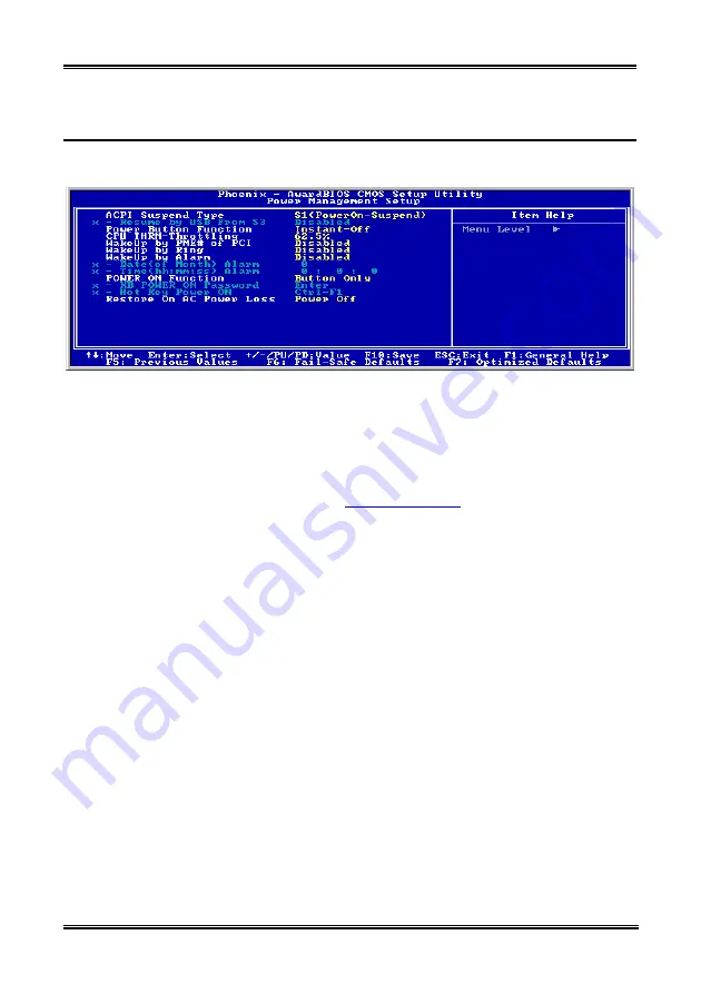
3-6.  Power Management Setup Menu 

This menu allows you to set up the power management in order to reduce power consumption. 


Figure 3-8. Power Management Setup Menu 

If you want ACPI (Advanced Configuration and Power Interface) functions to work normally, you should 
notice two things. One is your operating system must support ACPI. The second thing is that all devices 
and add-on cards in your system must fully support ACPI, both hardware and software (drivers). If you 
want to know if your devices or add-on cards support ACPI or not, please contact the device or add-on 
card manufacturer for more information. If you want to know more about ACPI specifications, please go 
to the address below for more detailed information: 

http://www.acpi.info/


ACPI requires an ACPI-aware operating system. ACPI features include: 

• 

Plug and Play (including bus and device enumeration) and APM functionality normally contained 
in the BIOS. 

• 

Power management control of individual devices, add-in cards (some add-in cards may require an 
ACPI-aware driver), video displays, and hard disk drives. 

• 

A Soft-off feature that enables the operating system to power off the computer. 

• 

Support for multiple wake-up events (see Table 3-1). 

• 

Support for a front panel power and sleep mode switch. Table 3-2 describes the system states based 
on how long the power switch is pressed, depending on how ACPI is configured with an 
ACPI-aware operating system. 

System States and Power States: 

Under ACPI, the operating system directs all system and device power state transitions. The operating 
system puts devices in and out of low-power states based on user preferences and knowledge of how 
devices are being used by applications. Devices that are not being used can be turned off. The operating 
system uses information from applications and user settings to put the system as a whole into a low-power 
state. 

BE7 Series 

Summary of Contents for BE7

Page 1: ...BE7 Series BE7 G BE7 S BE7 RAID BE7 B BE7 Socket 478 System Board User s Manual 4200 0329 02 Rev 1 00 ...

Page 2: ...al or consequential damages arising from any defect or error in this manual or product Product names appearing in this manual are for identification purpose only and trademarks and product names or brand names appearing in this document are the property of their respective owners This document contains materials protected under International Copyright Laws All rights reserved No part of this manua...

Page 3: ... 1 6 LAYOUT DIAGRAM BE7 1 7 CHAPTER 2 HARDWARE SETUP 2 1 2 1 INSTALL THE MOTHERBOARD 2 1 2 2 INSTALL PENTIUM 4 CPU AND HEATSINK SUPPORTING BASE 2 2 2 3 INSTALL SYSTEM MEMORY 2 3 2 4 CONNECTORS HEADERS AND SWITCHES 2 4 CHAPTER 3 BIOS SETUP 3 1 3 1 CPU SETUP SOFTMENU III 3 3 3 2 STANDARD CMOS FEATURES SETUP MENU 3 6 3 3 ADVANCED BIOS FEATURES SETUP MENU 3 9 3 4 ADVANCED CHIPSET FEATURES SETUP MENU 3...

Page 4: ...DIX D INSTALL LAN DRIVER D 1 APPENDIX E INSTALL USB 2 0 DRIVER E 1 APPENDIX F INSTALL SERIAL ATA RAID DRIVER FOR BE7 G BE7 S F 1 APPENDIX G HPT 372 SETUP FOR BE7 RAID G 1 APPENDIX H BIOS UPDATE GUIDE H 1 APPENDIX I HARDWARE MONITORING THE WINBOND HARDWARE DOCTOR UTILITY I 1 APPENDIX J INSTALLATION GUIDE FOR SUSPEND TO RAM J 1 APPENDIX K TROUBLESHOOTING NEED ASSISTANCE K 1 APPENDIX L HOW TO GET TEC...

Page 5: ...et 478 以方便安裝 Intel Pentium 4 CPU 您所 購買的 CPU 應已配備一組散熱套件及散熱片 如果沒 有 請購買專為 Pentium 4 Socket 478 設計的散熱套件 及散熱片 1 請找出 Socket 478 的位置 然後將散熱套件支座固 定在主機板上 注意 若果您使用專為 Pentium 4 設計的底座 請注意 底座上的金屬螺栓或墊片 若已安裝的話 請確定金屬 螺栓或墊片不會碰到印刷電路板上的電線或零件 2 請將 CPU 插座桿拉出至插座旁 然後將插座桿以 90 度角向上拉 請以正確的方向插入 CPU 由於 只能朝著一個固定的方向插入 CPU 因此如果遇到 阻礙時 切勿勉強用力 最後壓住 CPU 並且閂上 插座桿 3 請將散熱裝置的正面向著 CPU 放入 直至完全蓋 住 CPU 為止 4 將散熱裝置的支罩蓋在散熱裝置上 請確定支罩的 每邊四個鎖扣都已鎖入...

Page 6: ...DDR DIMM 記憶 體模組完全插入 DIMM 插槽時 模組退出 固定 夾 應該會將 DDR DIMM 記憶體模組自兩側卡緊並緊緊地 固定住記憶體模組 請依 DIMM1 DIMM3 插槽的順序 來安裝記憶體模組 最後 您必需將所有必需的裝置纜線連接到主機板上相關的連接頭或是連接器上面 以完成您系統 的硬體安裝動作 連接器 連接頭以及附加卡的安裝 在任何一部電腦機殼的裡面 都必需連接一些纜線與插頭 這些纜線與插頭通常都是一對一的連接 至主機板的連接埠上 您必需注意任何一條纜線的連接方向 如果可能的話 請一併注意連接埠第 一根針腳的位置 您將會安裝一些特殊功能的附加卡到主機板上面 像是 SCSI 卡或是 AGP 顯示 卡等等 當您將它們安裝到主機板上適當的插槽之後 請以螺絲將這些附加卡與機殼背板牢牢地固 定好 避免有鬆動的情況發生 如您想要瞭解相關且更為詳細的資訊 請參閱我們的完整版使用手冊...

Page 7: ...ァンのキットが付属しています 付属してい ない場合 Pentium 4 Socket 478 向けに特別に設計された キットをお求めください 1 Socket 478 を設置します ヒートシンクをマザーボー ド上のサポート台に固定してください 注意 Pentium 4 向けに特別に設計されたシャーシをお 使いの場合 金属スタッドやスペーサがすでにインスト ールされている場合 それらの場所に注意してくださ い 金属スタッドやスペーサがプリント基板線や PCB の 部品に触れないように気をつけてください 2 CPU のソケットレバーをソケットから横方向に引い て 90 度上に持ち上げます CPU を正しい方向に挿 入します CPU を挿入する際 余分な力を入れない でください 1 方向にだけ適合します CPU を下に 押しながら ソケットレバーをクローズします 3 ヒートシンクの面が CPU ...

Page 8: ...ケットにしっかりと押し込み モジュールが DDR DIMM ソケットに完全に差し込まれ ていることを確認します これらのモジュールに対して DIMM1 から DIMM3 まで順に差し込むようにお勧めします 次に すべての必要なデバイスケーブルをマザーボードの関連ヘッダとコネクタに接続して シ ステムのハードウェア取付けを終了する必要があります コネクタ ヘッダ スイッチおよびアダプタ コンピュータのケース内部には 複数のケーブルやプラグを接続できます これらのケーブルや プラグは 通常マザーボードにあるコネクタに 1 つずつ接続されます ケーブルの接続方向には 十分な注意を払い また必要に応じ コネクタの第 1 ピンの位置にも注目する必要があります SCSI アダプタ AGP アダプタのような特殊なニーズ向けには それに対応したアダプタを取り 付けてください アダプタをマザーボードのスロッ...

Page 9: ...gen Sie die Basis des Kühlblechs am Motherboard an Achtung Wenn Sie ein speziell für den Pentium 4 entworfenes Gehäuse verwenden achten Sie bitte auf die Lage der Metallbolzen oder Abstandhalter falls diese schon im Gehäuse angebracht sind Achten Sie darauf diese Metallbolzen bzw Abstandhalter nicht in Kontakt mit den gedruckten Schaltkreisen oder Teile auf dem PCB kommen zu lassen 2 Ziehen Sie de...

Page 10: ...mpfehlen wir Ihnen die Bestückung von DIMM1 zu DIMM3 in dieser Reihenfolge Danach müssen Sie alle nötigen Gerätekabel mit den entsprechenden Sockeln und Anschlüssen auf der Hauptplatine verbinden um die Hardwareinstallation Ihres Systems zu vervollständigen Anschlüsse Sockel Schalter und Adapter Im Inneren des Gehäuses findet man in jedem Computer viele Kabel und Stecker die angeschlossen werden m...

Page 11: ...m 4 Socket 478 1 Placez le Socket 478 Fixez la base support du dissipateur thermique sur la carte mère Attention Si vous utilisez un châssis conçu spécialement pour Pentium 4 veuillez faire attention à l emplacement des clous ou spacers métalliques si ceux ci sont déjà installés sur le châssis Faites attention de ne pas laisser les talons studs ou entretoises spacers métalliques en contact avec de...

Page 12: ...DDR DIMM Pour ces modules nous vous suggérons de remplir de DIMM1 à DIMM3 en respectant l ordre Ensuite vous aurez à connecter les câbles de tous les périphériques nécessaires dans les socles de connexion et connecteurs correspondants se trouvant sur la carte mère pour terminer l installation matérielle de votre système Connecteurs Socles de connexion Interrupteurs et Adaptateurs A l intérieur du ...

Page 13: ...1 Найдите на плате гнездо Socket 478 Зафиксируйте крепежное основание радиатора на системной плате Внимание При использовании корпуса специально предназначенного для Pentium 4 обратите внимание на расположение металлических вставок или распорок если они уже установлены в корпус Не допускайте контакта металлических вставок или распорок с проводниками или деталями печатной платы 2 Сместите рычаг гне...

Page 14: ...я этих модулей мы рекомендуем устанавливать память начиная с DIMM1 и далее по DIMM3 Подключите все необходимые кабели для подключения устройств к соответствующим разъемам на материнской плате чтобы завершить установку аппаратуры вашей системы Разъемы переключатели и адаптеры Внутри корпуса компьютера необходимо расположены несколько кабелей и вилок которые необходимо подключить Обычно эти кабели п...

Page 15: ...lizzare la presa Socket 478 Fissare la base di supporto dispersore di calore sulla scheda madre Attenzione Se si impiega un telaio progettato specificatamente per il processore Pentium 4 prestare attenzione all ubicazione delle borchie in metallo o degli spaziatori nel caso in cui siano già installati sul telaio Assicurarsi di non permettere alle borchie in metallo od agli spaziatori di entrare in...

Page 16: ...DIMM Per questi moduli si suggerisce di inserire con ordine i chip elettronici da DIMM1 a DIMM3 Per completare l installazione dell hardware del sistema bisogna collegare tutti i cavi delle attrezzature necessarie ai relativi collettori e connettori sulla scheda madre Connettori collettori interruttori ed adattatori All interno della copertura di ogni computer ci sono diversi cavi e prese che devo...

Page 17: ...E7 S BE7 RAID BE7 B BE7 5 Serial ATA 150 For BE7 G BE7 S Onboard Silicon Image Serial ATA PCI Controller Support 2 ports SATA 150 1 5G bps 6 ATA133 RAID For BE7 RAID HighPoint HPT372 IDE controller Supports Ultra ATA 133MB sec data transfer rate Supports RAID 0 Stripping mode for boosting performance mode Supports RAID 1 Mirroring mode for data security mode Supports RAID 0 1 Stripping and Mirrori...

Page 18: ... connector AUDIO1 connector Rear Left Rear Right Center Subwoofer AUDIO2 connector Mic In Line In Front Left Front Right 2 x USB 1 x RJ 45 LAN Connector 11 Miscellaneous ATX form factor Hardware Monitoring including Fan Speed Voltages CPU and system temperature and one thermal header for other devices temperature monitoring Supports Wake Up by LAN Modem Ring RTC Alarm Keyboard and Mouse Power On S...

Page 19: ...Introduction 1 3 1 2 Layout Diagram BE7 G User s Manual ...

Page 20: ...1 4 Chapter 1 1 3 Layout Diagram BE7 S BE7 Series ...

Page 21: ...Introduction 1 5 1 4 Layout Diagram BE7 RAID User s Manual ...

Page 22: ...1 6 Chapter 1 1 5 Layout Diagram BE7 B BE7 Series ...

Page 23: ...Introduction 1 7 1 6 Layout Diagram BE7 User s Manual ...

Page 24: ...1 8 Chapter 1 1 8 Chapter 1 BE7 Series BE7 Series ...

Page 25: ... attached on and at the same time prevented from short circuits There are two ways to attach the motherboard to the chassis base use with studs or use with spacers Figure 2 1 shows the shape of studs and spacers There may be several types but all look similar In principle the best way to attach the board is to use with studs Only if you are unable to do this should you attach the board with spacer...

Page 26: ... socket lever sideways away from the socket and then upwards to 90 degree Insert the CPU with the correct orientation Do not use extra force to insert CPU it only fit in one orientation Closing down the socket lever while holding down the CPU 3 Put the heatsink faces down onto the CPU until it completely covers the CPU 4 Put the heatsink supporting cover onto the heatsink Make sure all the four lo...

Page 27: ...tatic electricity can damage the electronic components of the computer or optional boards Before starting these procedures ensure that you are discharged of static electricity by touching a grounded metal object briefly 1 Power off the computer and disconnect the AC power cord 2 Locate the DDR DIMM slot 3 Push both ejector tabs of the DDR DIMM slot outward Figure 2 4 Memory module installation 4 I...

Page 28: ...hapter 1 for all the position of connectors and headers on the board that you may refer to All the connectors headers and switches mentioned here are depending on your system configuration Some features you may or may not have to connect or to configure depending on the peripherals you have connected WARNING Always power off the computer and unplug the AC power cord before adding or removing any p...

Page 29: ...Hardware Setup 2 5 2 FAN Connectors FAN1 Power Fan FAN2 Chassis Fan FAN3 CPU Fan FAN1 CPU Fan FAN2 Chassis Fan FAN3 Power Fan User s Manual ...

Page 30: ...rt pin 2 and pin 3 only when you want to clear the CMOS memory The default setting is pin 1 and pin 2 shorted for normal operation NOTE Turn the power off first including the 5V standby power before clearing the CMOS memory Failing to do so may cause your system to work abnormally or malfunction BE7 Series ...

Page 31: ...provides totally six USB 2 0 ports controlled by ICH4 Two of them are through the onboard USB connectors four of them are capable through these two headers Pin Pin Assignment Pin Pin Assignment 1 VCC 2 VCC 3 Data0 4 Data1 5 Data0 6 Data1 7 Ground 8 Ground 9 NC 10 NC User s Manual ...

Page 32: ... for connecting switches and LED indicators on the chassis front panel Watch the power LED pin position and orientation The mark align to the pin in the figure below stands for positive polarity for the LED connection Please pay attention to connect these headers A wrong orientation will only cause the LED not lighting but a wrong connection of the switches could cause system malfunction BE7 Serie...

Page 33: ...Connects to the System Speaker cable of chassis Pin 2 4 SP LED Connects to the Suspend LED cable if there is one of chassis front panel Pin 6 8 PWR ON Connects to the Power Switch cable of chassis front panel Pin 16 18 20 PWR LED Connects to the Power LED cable of chassis front panel Pin 22 24 KEYLOCK Connects to the Keylock cable if there is one of chassis front panel User s Manual ...

Page 34: ...e extenson cable provided with the chassis To use the audio connector at rear panel disconnect the extension cable attach the jumpers back at pin 5 6 and pin 9 10 default setting Pin Pin Assignment Pin Pin Assignment 1 Audio Mic 2 Ground 3 Audio Mic Bias 4 VCC 5 Speaker Out Right Channel 6 Speaker Out Right Channel Return 7 X 8 NC 9 Speaker Out Left Channel 10 Speaker Out Left Channel Return 11 Gr...

Page 35: ... transfer If more than one master simultaneously tries to control the bus an arbitration procedure decides which master gets priority 9 JP1 Thermal Sensor Header This connector is a thermal sensor connector used for detecting the system environmental temperature It may also be called a system temperature detector You can attach one end of a two threaded thermal cable to this header and attach the ...

Page 36: ...2 12 Chapter 2 10 CD1 AUX1 Internal Audio Connector These connectors connect to the audio output of internal CD ROM drive or add on card BE7 Series ...

Page 37: ...dware Setup 2 13 11 AGP1 Accelerated Graphics Port Slot This slot supports an optional AGP graphics card up to AGP 4X mode Please refer to our Web site for more information on graphics cards User s Manual ...

Page 38: ...sk drives connection Connect the single end at the longer length of ribbon cable to this FDC1 and the two connectors on the other end to the floppy disk drives Generally you need only one floppy disk drive in your system Note The red line on the ribbon cable should be aligned with pin 1 on this connector BE7 Series ...

Page 39: ...Hardware Setup 2 15 13 IDE1 IDE2 and IDE3 IDE4 Connectors User s Manual ...

Page 40: ...configure the second drive to Slave mode after the first Master drive Please refer to the drives documentation for jumper settings The first drive connected to IDE1 is usually referred to as Primary Master and the second drive as Primary Slave The first drive connected to IDE2 is referred to as Secondary Master and the second drive as Secondary Slave Keep away from connecting one legacy slow speed...

Page 41: ...A Connector For BE7 G BE7 S These two connectors are provided to attach one serial ATA device at each channel through Serial ATA cable It is also possible to connect legacy IDE hard disk through an optional SERILLEL Converter User s Manual ...

Page 42: ...em mouse or other devices that support this communication protocol OPT1 This connector provides an S PDIF out connection through optical fiber to digital multimedia devices AUDIO1 R L R R Rear Left Rear Right Connects to the rear left and rear right channel in the 5 1 channel audio system Cen Sub Center Subwoofer Connects to the center and subwoofer channel in the 5 1 channel audio system AUDIO2 M...

Page 43: ...MOS data in Chapter 2 When you start the computer the BIOS program controls it The BIOS first operates an auto diagnostic test called POST Power On Self Test for all of the necessary hardware It then configures the parameters of the hardware synchronization and detects all of the hardware Only when these tasks are completed does it give up control of the computer to the next level which is the ope...

Page 44: ...aying that his or her CMOS DATA was lost What is the CMOS Is it important The CMOS is the memory used to store the BIOS parameters that you have configured This memory is passive You can read its data and you can also store data in it But this memory has to be powered by a battery in order to avoid any loss of its data when the computer is turned off Since you may have to change the CMOS battery w...

Page 45: ... the CPU type CPU Operating Speed This option sets the CPU speed In this field the CPU speed is indicated like this CPU Speed External Clock x Multiplier Factor Select the CPU speed according the type and speed of your CPU Normally we do not recommend that you use the User Define option to setup CPU speed and multiplier factors This option is for setup of future CPUs whose specifications are still...

Page 46: ...z fixed and 33MHz fixed The default setting is Ext Clock 3 Multiplier Factor The multiplier factors for this motherboard are x8 x9 x10 x11 x12 These factors vary with the different type and specification of the CPU installed NOTE Some processors might have this multiplier factor locked so there is no way to choose a higher multiplier factor DRAM Ratio H W Strap This item sets the external hardware...

Page 47: ...ince you have to open the computer case when you change the CPU it would be a good idea to use the CMOS clearing jumper to erase the parameters of the original CPU and to enter BIOS Setup to set up CPU parameters again ATTENTION After setting up the parameters and leaving the BIOS SETUP and having verified that the system can be booted do not press the Reset button or turn off the power supply Oth...

Page 48: ...etup Screen Shot Date mm dd yy You can set the date in this item month mm date dd and year yy Time hh mm ss You can set the time in this item hour hh minute mm and second ss IDE Primary Master Slave and IDE Secondary Master Slave These items have a sub menu to let you choose further options You can refer to figure 3 4 to check what options are available Figure 3 4 IDE Primary Master Setup Screen S...

Page 49: ...m you can according to your operating system choose four operating modes NORMAL LBA LARGE Auto The HDD auto detection option in the sub menu will automatically detect the parameters of your hard disk and the mode supported Auto Lets the BIOS detect your HDD access mode and make the decisions Normal mode Standard normal mode supports hard disks of up to 528MB or less This mode directly uses positio...

Page 50: ...s or logical blocks that function as the smallest units of data permit You can configure this item to sectors per track The minimum number you can enter is 0 the maximum number you can enter is 255 Drive A Drive B If you have installed the floppy disk drive here then you can select the type of floppy drive it can support Six options are available None 360K 5 25in 1 2M 5 25in 720K 3 5in 1 44M 3 5in...

Page 51: ...e OS and applications This option is for CPU with Hyper Threading Technology only For more information on Hyper Threading Technology please visit Intel Web site at http www intel com homepage land hyperthreading htm http www intel com design chipsets ht Quick Power On Self Test After the computer has been powered on the BIOS of the motherboard will run a series of tests in order to check the syste...

Page 52: ...t Settings Off At boot up the Numeric Keypad is in cursor control mode Disable Unused PCI Clock This option disables the clock of PCI slot that is not in use Security Option This option can be set to System or Setup The default setting is Setup After you have created a password through PASSWORD SETTING this option will deny access to your system System or modification of computer setup BIOS Setup ...

Page 53: ...ou use OS 2 select OS2 if you are using another operating system select Non OS2 The default setting is Non OS2 Report No FDD For OS When you are running some older Windows version without floppy drive set this item to Yes Otherwise set it to No The default setting is No Delay IDE Initial Secs This item is used to support some old models or special types of hard disks or CD ROMs They may need a lon...

Page 54: ...the consequences of your changes The first chipset settings deal with CPU access to DRAM The default timings have been carefully chosen and should only be altered if data is being lost Such a scenario might well occur if your system has mixed speed DRAM chips installed In such a case greater delays may be required to preserve the integrity of the data held in the slower memory chips DRAM Timing Se...

Page 55: ...5M and 16M and this memory block has a size of 1M We recommend that you disable this option Delayed Transaction Two options are available Enabled and Disabled The default setting is Disabled Set the option to enabled or disabled PCI 2 1 features including passive release and delayed transaction for the chipset This function is used to meet the latency of PCI cycles to or from the ISA bus This opti...

Page 56: ... for two IDE channels If you choose Disabled it will affect the settings of four items not available For example if you disabled the OnChip IDE 1 Controller you will also disable the Master Slave Drive PIO Mode and Master Slave Drive Ultra DMA Master Slave Drive PIO Mode Six options are available Auto Mode 0 Mode 1 Mode 2 Mode 3 Mode 4 The five IDE PIO Programmed Input Output items let you set a P...

Page 57: ...ip IDE 2 Controller The description is same as the OnChip IDE 1 Controller OnChip PCI Device s Press Enter key to enter the OnChip PCI Device s menu OnChip USB Controller Two options are available Enabled and Disabled The default setting is Enabled This motherboard provides two Universal Serial Bus USB ports thus supporting USB devices If you don t want to use USB devices set it to Disabled then t...

Page 58: ...A133RAID controller When set to Enabled two additional channels will be provided for adding high performance devices to system Serial ATA Controller For BE7 G and BE7 S This item selects the onboard Serial ATA controller When set to Enabled two additional channels will be provided for adding high performance devices to system Onboard FDD Controller Two options are available Enabled and Disabled Th...

Page 59: ...e to find out which setting is correct Use IR Pins Two options are available RxD2 TxD2 and IR Rx2Tx2 The default setting is IR Rx2Tx2 If you choose RxD2 TxD2 your motherboard must support a COM port IR KIT connection Otherwise you can only choose the IR Rx2Tx2 to use the IR header on your motherboard to connect your IR KIT Please use the default setting Onboard Parallel Port Sets the I O address a...

Page 60: ...cluding bus and device enumeration and APM functionality normally contained in the BIOS Power management control of individual devices add in cards some add in cards may require an ACPI aware driver video displays and hard disk drives A Soft off feature that enables the operating system to power off the computer Support for multiple wake up events see Table 3 1 Support for a front panel power and ...

Page 61: ...Generally ACPI has six states System S0 state S1 S2 S3 S4 S5 S1 and S3 states are described below The S1 POS State POS means Power On Suspend While the system is in the S1 sleeping state its behavior is as described below The processor is not executing instructions The processor s complex context is maintained Dynamic RAM context is maintained Power Resources are in a state compatible with the sys...

Page 62: ...es that could be left ON in the S2 state might not be available to the S3 state As such additional devices can be required to be in logically lower D0 D1 D2 or D3 state for S3 than S2 Similarly some device wake events can function in S2 but not S3 Because the processor context can be lost while in the S3 state the transition to the S3 state requires that the operating software flush all dirty cach...

Page 63: ... and USB connection Mouse Left Mouse Right means you need to double click the mouse left right button for the computer to power on You also need to note the compatibility issue with your PS 2 mouse Some PS 2 mice cannot wake up the system because of compatibility problems Also if the specs of your keyboard are too old it may fail to power on KB Power ON Password This option allows you to set a pas...

Page 64: ...rt memory information of the system This is a specification and a feature specific to the Plug Play BIOS Resources Controlled By Two options are available Auto ESCD and Manual Default setting is Auto ESCD When the setting is Auto ESCD the IRQ Resources and Memory Resources can not be changed When resources are controlled manually the IRQ Resources and Memory Resources can then be changed PCI PnP d...

Page 65: ...5 it may cause the USB port to malfunction or have other problems PCI Latency Timer CLK This option selects the controls for the amount of time that the ICH arbiter allows a PCI initiator to perform multiple back to back transactions on the PCI bus The options are 32 64 96 128 160 192 224 and 248 PCI Clocks The default setting is 32 PCI Clocks PIRQ_0 Use IRQ No PIRQ_7 Use IRQ No The options are Au...

Page 66: ...d you can check the fan speeds and power supply voltages of your computer system The features are useful for monitoring all the important parameters within your computer system We call it the PC Health Status Figure 3 11 PC Health Status Screen Shot FAN Fail Alarm Selectable This item lets you select which one of the fans will be monitored for malfunction The options are Disabled PWRFAN CPUFAN CHA...

Page 67: ...rning message to the PC speakers of when the temperature goes beyond either limit You can select the temperatures you want The ranges are from 30 C 86 F to 120 C 248 F default setting is 75 C 167 F All Voltages Fans Speed and Thermal Monitoring These unchangeable items list the current status of the CPU and environment temperatures fan speeds and system power voltage NOTE The hardware monitoring f...

Page 68: ... Pressing Y loads the BIOS default values for the most stable minimal performance system operations 3 10 Load Optimized Defaults Figure 3 13 Load Optimized Defaults Screen Shot When you press Enter on this item you get a confirmation dialog box with a message similar to Load Optimized Defaults Y N N Pressing Y loads the default values that are factory settings for optimal performance system operat...

Page 69: ...er the password A message will confirm the password will be disabled Once the password is disabled the system will boot and you can enter Setup freely PASSWORD DISABLED When a password has been enabled you will be prompted to enter it every time you try to enter Setup This prevents an unauthorized person from changing any part of your system configuration Additionally when a password is enabled yo...

Page 70: ...he next time you boot your computer the BIOS configures your system according to the Setup selections stored in CMOS After saving the values the system is restarted again 3 13 Exit Without Saving Figure 3 17 Exit Without Saving Screen Shot Pressing Enter on this item asks for confirmation Quit without saving Y N Y This allows you to exit Setup without storing in CMOS any change The previous select...

Page 71: ...llow its on screen instruction Insert the Driver Utility CD into CD ROM drive it should execute the installation program automatically If not double click the execution file at the main directory of this CD to enter the installation menu After entering the installation menu move your curser to Driver tab Click Intel Chipset Software Utility The following screen appears 1 Click Next 2 Click Yes Cli...

Page 72: ...A 2 Appendix A A 2 Appendix A BE7 Series BE7 Series ...

Page 73: ...sed on Windows XP operating system For those of other OS please follow its on screen instruction Insert the Driver Utility CD into CD ROM drive it should execute the installation program automatically If not double click the execution file at the main directory of this CD to enter the installation menu After entering the installation menu move your curser to Driver tab Click Intel Application Acce...

Page 74: ...B 2 Appendix B 5 Choose Yes I want to restart my computer now and click Finish to complete setup BE7 Series ...

Page 75: ...execution file at the main directory of this CD to enter the installation menu After entering the installation menu move your curser to Driver tab Click RealTek ALC650 Audio Driver The following screen appears 1 Click Next 2 Click Continue Anyway 3 Choose Yes I want to restart my computer now and click Finish to complete setup 4 After the system restarted a shortcut icon appears at the right corne...

Page 76: ...C 2 Appendix C Note To keep a normal operation of 5 1 speakers output please do not change the settings of Line In and Mic In in this menu BE7 Series ...

Page 77: ...k the execution file at the main directory of this CD to enter the installation menu For BE7 and BE7 RAID After entering the installation menu move your curser to Driver tab Click RealTek LAN Driver The following screen appears 1 Click Next 2 Click Finish to complete setup For BE7 S and BE7 B After entering the installation menu move your curser to Driver tab Click Broadcom 10 100 LAN Driver The f...

Page 78: ...r finished the driver installation check the Network adapters in the Device Manager You will find the Broadcom 440x 10 100 Integrated Controller is successfully installed Select Broadcom 440x 10 100 Integrated Controller Right click your mouse to enter its properties 2 Select Advanced tab Move your cursor to select the Wake Up Capabilities property option and then set the value option to Magic Fra...

Page 79: ...indows 2000 After entering the installation menu move your curser to Driver tab Click Broadcom Gigabit LAN Driver The following screen appears 1 Click MAKEDISK UTILITY 2 Click Next Click Yes 3 Select Windows 2000 Click Next 4 5 Insert a blank floppy disk to A drive You may also create a new directory in your hard disk by clicking Browse Click Next to start copying files User s Manual ...

Page 80: ...sk 7 The setup wizard finish copying files to floppy disk Click OK to exit 8 Check Device Manager Click Ethernet Controller 9 Select Driver tab in the Ethernet Controller Properties Click Update Driver 10 The upgrade wizard appears Click Next to continue BE7 Series ...

Page 81: ... Select Search for a suitable driver for my device Click Next 12 Select Floppy disk drives Click Next 13 Click Next Click Finish 14 15 Back to the Ethernet Controller Properties Click Close to finish driver update User s Manual ...

Page 82: ...D 6 Appendix D 16 Check Device Manager again Broadcom NetXtreme Gigabit Ethernet is successfully upgraded BE7 Series ...

Page 83: ...CD into CD ROM drive it should execute the installation program automatically If not double click the execution file at the main directory of this CD to enter the installation menu After entering the installation menu move your curser to Driver tab Click USB 2 0 Driver The following screen appears 1 Choose Yes I want to restart my computer now and click Close to reboot the system 2 Click Next Clic...

Page 84: ...E 2 Appendix E BE7 Series ...

Page 85: ...drive it should execute the installation program automatically If not double click the execution file at the main directory of this CD to enter the installation menu After entering the installation menu move your curser to Driver tab Click Serial ATA RAID Driver The following screen appears 1 Click Next 2 Click Continue Anyway 3 Choose Yes I want to restart my computer now and click Finish to comp...

Page 86: ...F 2 Appendix F F 2 Appendix F BE7 Series BE7 Series ...

Page 87: ...n instruction Insert the Driver Utility CD into CD ROM drive it should execute the installation program automatically If not double click the execution file at the main directory of this CD to enter the installation menu After entering the installation menu move your curser to Driver tab Click HPT 372 Driver The following screen appears 1 Click Next 2 Click Continue Anyway to continue Click Finish...

Page 88: ...ick Yes 7 Click Next 8 Click Next 9 Click Yes if you want to add a shortcut to startup folder Click Finish to end the setup 10 11 Choose Yes I want to restart my computer now and click Finish to complete setup BE7 Series ...

Page 89: ...AID 0 1 For the striping operation the identical drives can read and write data in parallel to increase system performance The Mirroring operation creates a complete backup of your files Striping with Mirroring operation offers both read write performance and fault tolerance After completed the installation of HPT37X driver you have to enable the RAID function in BIOS setup menu Enter the Advanced...

Page 90: ...ill result in both hard disks becoming blank Option 1 Create RAID This item allows you to create a RAID array Array Mode This item allows you to select the appropriate RAID mode for the desired array There are four modes to choose NOTE It is highly recommended to attach hard disks with the same model in reaching the RAID performance Striping RAID 0 This item is recommended for high performance usa...

Page 91: ... press Enter key to enter the sub menu as shown below Select Source Disk This item selects the source disk The size of source disk must be smaller or equal to the size of target disk Select Target Disk This item selects the target disk The size of target disk must be greater or equal to the size of source disk Start Duplicating Process After you had selected this item the BIOS setting will take up...

Page 92: ...n Menu and press Enter to confirm 2 In the Channel Status select the channel you would like to set and press Enter an asterisk mark appears in the parentheses to indicate that the channel has been selected 3 Choose the mode from the pop up menu You can choose from PIO 0 4 MW DMA 0 2 and UDMA 0 5 Option 7 Set Boot Disk This item allows you to select boot disk among hard disk s To set disk mode 1 Se...

Page 93: ...the model name and version number of this motherboard You can find a sticker with model name and version number on one slot or at the back of the motherboard 2 Find out the current BIOS ID For example in this case the current BIOS ID is 00 If you already have the latest BIOS no any update action is necessary If your BIOS is not the latest BIOS go on to the next step User s Manual ...

Page 94: ... will self extract to bin file 5 Make a bootable floppy disk and copy the necessary files onto it You may make a floppy disk bootable either in Explorer or in the DOS prompt mode After formatting and transferring the system to the floppy disk copy two files into it One is the BIOS flash utility awdflash exe and the other is the decompressed BIOS binary file BE7 Series ...

Page 95: ...BIOS Update Guide H 3 6 Boot off floppy disk Please set the first boot sequence as floppy in BIOS and boot off the floppy disk User s Manual ...

Page 96: ...ile Otherwise it may cause system malfunctions Please do not use the Award flash memory writer version earlier than Version 7 52C to flash the BIOS Otherwise it may cause flash fail or un anticipated problems During the updating the progress will be measured by white blocks The last four blue blocks of the flash update process represent the BIOS boot block The BIOS boot block is used to prevent th...

Page 97: ...ce any item is out of its normal range a warning message pops up reminding you to take proper measures The installation procedures and screen shots in this section are based on Windows XP operating system For those of other OS please follow its on screen instruction Insert the Driver Utility CD into CD ROM drive it should execute the installation program automatically If not double click the execu...

Page 98: ...vate it in the Configuration page Shutdown Choosing this button will shutdown the computer Help You can read more information and self diagnose simple problems If the warning message pops up due to the wrong warning limit you can adjust it in the Configuration option For example if you set the temperature high limit to 40 C you will easily exceed the proper temperature Pay attention to two things ...

Page 99: ...t went to sleep When idle STR enabled systems consume only a small fraction of the power used for full operation Instead of shutting down the system to save power when not in use and then having to reboot later users can let the STR function take over and not have to worry about using power to run all the electronics fans and disks When needed a PC with STR function can restore all applications an...

Page 100: ... Computer 2 Click Stand by Method 2 Define the chassis s Power button to initiate STR sleep Mode 1 Open Control Panel and then enter Power Options 2 Select Advanced tab Set the Power Buttons option to Stand by Restart your computer to put these settings into effect Now you will only need to press the Power button on the front panel of the chassis when you want to put your computer into STR sleep m...

Page 101: ...e CMOS data recover the hardware default status and then make the motherboard working again No need to bother returning the motherboard to where you bought from or go through an RMA process Step 1 Switch off the power supply unit and then switch it on again after one minute If there is no power switch on the power supply unit disconnect its power cord for one minute and then connect it back Press ...

Page 102: ...y to start the system each time you insert a card until the system will not start Keep the VGA card and the interface card that caused the problem inserted on the motherboard remove any other cards or peripheral and start again If you still cannot start note the information related to both cards in the add on Card space provided and don t forget to indicate the motherboard model version BIOS ident...

Page 103: ...ur HDD s specify if the HDD is using IDE1 or IDE2 If you know the disk capacity indicate it and check in case you give no indication we will consider that your HDD is IDE1 Master Example In the HDD space check the box in the Brand space write Seagate in the Specifications space write ST31621A 1 6GB 8 CD ROM Drive Indicate the brand and specifications of your CD ROM drive Specify if it uses IDE1 or...

Page 104: ...ll known issue of Windows 95 98 s FDISK utility If an IBM 75GB hard disk DTLA 307075 only gets 7768MB in Windows 95 98 s FDISK utility please contact Microsoft for a latest version of FDISK utility or download IBM s Disk Manager DiskGo 2 5 to fix it For windows 2000 there is no such a 64GB issue http www storage ibm com techsup hddtech welcome htm Q How to create a striping and mirror array RAID 0...

Page 105: ...ALTED when booting A There isn t any activated primary partition in you system Please use FDISK or any other utilities to create set one Do Don t 1 Do always use the same model drives to achieve best quality and performance Different firmware has different timing characteristic thus may somewhat decrease the RAID performance 2 If you have two drives do connect them on two different channels as mas...

Page 106: ...me Phone Number Contact Person Fax Number E mail Address Model BIOS ID Motherboard Model No DRIVER REV OS Application Hardware Name Brand Specifications CPU HDD IDE1 IDE2 CD ROM Drive IDE1 IDE2 System Memory ADD ON CARD Problem Description BE7 Series ...

Page 107: ...ts have the best quality and compatibility In case you need service or technical support please understand the constraint we have and always check with the reseller who sold the product to you first To expedite service we recommend that you follow the procedures outlined below before contacting us With your help we can meet our commitment to provide the best service to the greatest number of ABIT ...

Page 108: ...tegrated and sold the system to you They should know best what your system configuration is and your problem They should have reasonable return or refund policies How they serve you is also a good reference for your next purchase 6 Contacting ABIT If you feel that you need to contact ABIT directly you can send email to the ABIT technical support department First please contact the support team for...

Page 109: ...8 Fax 44 1438 226333 sales abitcomputer co uk technical abitcomputer co uk Germany Benelux Belgium Netherlands Luxembourg Denmark Norway Sweden Finland and Switzerland AMOR Computer B V ABIT s European Office Van Coehoornstraat 7 5916 PH Venlo The Netherlands Tel 31 77 3204428 Fax 31 77 3204420 sales abit nl technical abit nl Austria Czech Romania Bulgaria Yugoslavia Slovakia Slovenia Croatia Bosn...

Page 110: ...92974 Paris La Defense cedex France Fax 33 1 5858 0047 http www abit com tw All other territories not covered above please contact Taiwan Head Office When contacting our headquarters please Note we are located in Taiwan and we are 8 GMT time In addition we have holidays that may be different from those in your country ABIT Computer Corporation No 323 YangGuang St Neihu Taipei 114 Taiwan Tel 886 2 ...

Page 111: ...on any compatibility problem that is reported to us giving detailed system configuration information and error symptoms will receive the highest priority For the other questions we regret that we may not be able to reply directly But your questions may be posted to the Internet news group in order that a larger number of users can have the benefit of the information Please check the news group fro...

Page 112: ...L 6 Appendix L Thank You ABIT Computer Corporation http www abit com tw BE7 Series ...

Reviews: