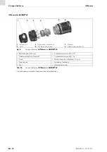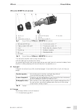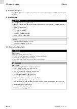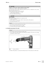
EN - 14
BAL.0523.0 • 2019-10-17
6 Commissioning
iSTM mini
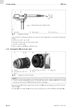
In order to determine the optimum position of the wire feeder at extreme welding positions, we recommend the following axis
positions:
A6 >
±
100°, A5 >
±
90°, A4 >
±
100°
This procedure avoids extreme stress on the cable assembly.
1
Loosen the wire feeder
2
in the specified direction.
6.2.1 Attaching the iSTM mini to the robot
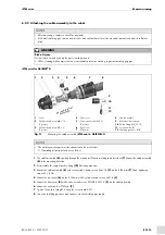
Mount the iSTM mini
with eight cylinder head screws M4 × 12
and a max. tightening torque of M = 4 Nm on the
welding robot
.
The pin hole
in the welding robot
serves as a reference point between the iSTM mini
and welding robot
.
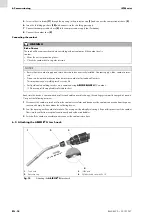
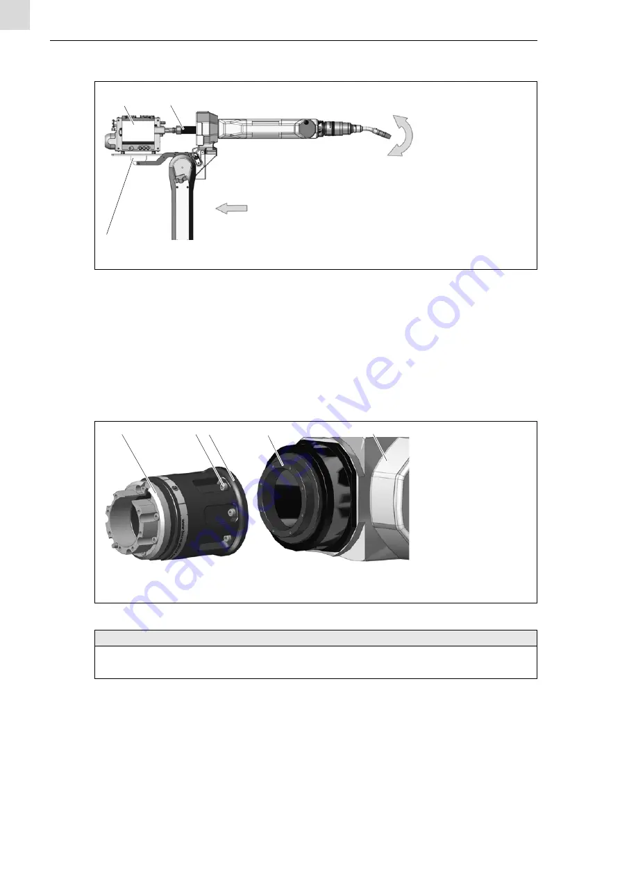
1
Wire feeder
2
Cable assembly
3
Wire feeder mount
Fig. 9
Standard axis positions
Mounting direction of the cable assembly
1
3
2
J5
(A5)
−90
1
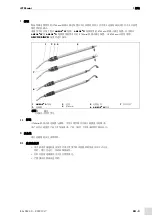
iSTM mini
2
Cylinder head screws M4 × 12 (8
pieces)
3
Intermediate flange for iSTM mini
4
Pin hole
5
Welding robot
Fig. 10
Attaching the
iSTM mini
to the robot
NOTICE
• The type of intermediate flange
used for the iSTM mini
model. The number
and size of cylinder head screws
used also depend on the welding robot.
1
2 3
5
4


