background image


EN - 6

4 Putting into operation

Welding torch ERGO

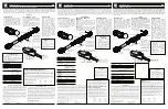
4.2 Mounting the wire guide

4.2.1 Liner

For using steel wires.

1

Stretch out the cable assembly and remove the gas nozzle and contact tip 
from the torch neck.

2

Unscrew the nut from the central connector and slide the liner through the 
wire conduit up to the retaining nipple.

3

Tighten the nut again by hand and cut off any excess liner flush with the 
torch neck or tip adaptor.

4

Unscrew the nut and pull out the liner.

5

Sharpen the start of the liner to an angle of approx. 40° and deburr the 
edge.

6

Slide the sharpened liner through the wire conduit up to the retaining nipple 
then screw down the nut and tighten it using a switch key wrench.

7

Screw in the contact tip and attach the gas nozzle.

4.2.2 PA liner

For using aluminium, copper, nickel and stainless steels.

1

Use the 

ABICOR BINZEL

 sharpener to sharpen the start of the PA liner to 

an angle of about 40°. Then slide the PA liner through the wire conduit until 
you feel it reach the contact tip.

2

Slide the clamp nipple, O-ring and nut onto the PA liner and tighten the nut 
under tension.

3

Mark any excess length of PA liner in front of the wire feed rolls and use the 

ABICOR BINZEL

 cutter to cut it off at the mark.

4

Sharpen the cutting point.

4.3 Connecting the cable assembly

1

Attach the central connector to the central socket on the wire feed unit and 
secure it with the connection nut.

2

Properly mount the connections for coolant supply/return, shielding gas 
and the control lead plug.

NOTICE

• For PA liners with an outer diameter of 4.00 mm, the capillary tube in the 

distance adaptor must be replaced with a guide tube.

Summary of Contents for ERGO Series

Page 1: ...C H N O L O G Y F O R T H E W E L D E R S W O R L D www binzel abicor com Z E R T IF I Z I E R T E S Q M S Y S T E M DIN EN ISO 9001 S EN Operating instructions EN MIG MAG Welding torch ERGO GB 15579...

Page 2: ...ditions of the Instructions All trademarks mentioned in the operating instructions are the property of their respective owners 1 Designated use EN 3 2 Technical data EN 3 3 Safety instructions EN 4 3...

Page 3: ...Ambient conditions during operation Type of voltage DC DC polarity of the electrodes Usually positive Shielding gas DIN EN 439 CO2 and mixed gas M21 Wire types Commercially available round wires Volta...

Page 4: ...ting instructions for the power source or the documentation for other peripheral devices Standard length L 3 00 m 4 00 m 5 00 m Coolant connection Plug in nipple nom diam 5 Cooling unit power Min 800...

Page 5: ...assembly disassembly and repair work Switch off the power source Close the gas supply Close the compressed air supply Disconnect the mains plug CAUTION Risk of injury Puncture or cut in wounds may be...

Page 6: ...tip and attach the gas nozzle 4 2 2 PA liner For using aluminium copper nickel and stainless steels 1 Use the ABICOR BINZEL sharpener to sharpen the start of the PA liner to an angle of about 40 Then...

Page 7: ...y shorten your welding torch s service life For liquid cooled welding torches we recommend using ABICOR BINZEL BTC coolant The cooling system must be purged of any air each time the device is commissi...

Page 8: ...flow time has passed and then switch off the power source 3 Close the valve on the shielding gas cylinder 8 Maintenance and cleaning NOTICE As liquid cooled cable assemblies start to leak when they o...

Page 9: ...he machine side to the wire feed unit NOTICE The specified maintenance intervals are guidance values and refer to single shift operation Maintenance and cleaning work may only be carried out by qualif...

Page 10: ...EN 10 8 Maintenance and cleaning Welding torch ERGO...

Page 11: ...EN 11 Welding torch ERGO 8 Maintenance and cleaning...

Page 12: ...R T H E W E L D E R S W O R L D www binzel abicor com Alexander Binzel Schweisstechnik GmbH Co KG Postfach 10 01 53 D 35331 Giessen Tel 49 0 64 08 59 0 Fax 49 0 64 08 59 191 Email info binzel abicor c...

Reviews: