


36
5.3.1. Control wiring
During routine maintenance for control wiring, a visual
inspection of the hardware should be performed and a low-
frequency withstand voltage testing performed, and 3 manual
operations should be conducted. Disconnect control power
before verifying secondary hardware and before low-frequency
withstand voltage testing.
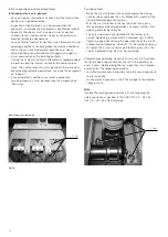
Remove the front cover with a screwdriver. Correct any
loose or missing mounting hardware. Verify the ground wire
connection to the frame and all connectors' alignment and
snugness on the electrical components. Visually inspect the
secondary plug and correct any pins that may have become
displaced.
To verify the integrity of the secondary insulation, perform the
following low-frequency withstand voltage test:
1. Disconnect control power.
2. Connect all pins from the secondary to a test wire.
3. Connect test wire to the high potential lead of the test
machine.
4. Ground the circuit-breaker frame.
5. Start machine with output potential at 0 (zero) VAC RMS.
6. Increase the potential to the required insulation test voltage
(1125 VAC RMS).
7. Hold for one minute.
8. Reduce potential to 0 (zero) VAC and turn off machine.
A successful withstand testing indicates satisfactory insulation
strength of the secondary circuit. Failing insulation will not
sustain the voltage across the secondary. Replace the
circuit-breaker control wiring if the insulation fails during low-
frequency withstand voltage testing.
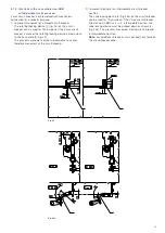
Replace the front cover before operation. Verify the operation
with 2-5 electrical operations in the Test position or with a
remote power supply.
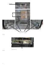
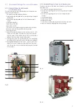
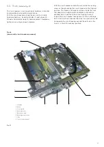
5.3.2. Primary circuit assembly
(Pole)
During routine maintenance for the primary circuit, a visual
inspection of the hardware and a low-frequency withstand
voltage testing, and lubrication of the primary contacts should
occur as outlined hereinafter.
All insulation material should be clean and free of cracks and
replace damaged parts.
Dirt or dust may create a dielectric path to ground on the
insulation. Remove dust and dirt with a clean, lint-free cloth.
Apply distilled water to the cloth to remove any difficult
dirt. DO NOT return the circuit-breaker into service until the
insulation surfaces are completely dry to prevent external
flash-over from the live part to live part or to ground.
Lubrication on the primary contacts should be inspected
during routine maintenance. use only grease Isoflex Topas
Nb52 (Abb No. GCE0007249 P100, 1 Pt. can).
To verify the integrity of the primary insulation, perform the
following low-frequency withstand voltage test:
1. Close the circuit-breaker (no control power supplied)
• Connect the high potential lead to one pole.
• Ground the remaining poles and the circuit-breaker
frame.
2. Start machine with output potential at 0 (zero) VAC.
3. Increase the potential to the required voltage (see Table 3;
note that new condition test is a factory test only and is
not valid for field condition tests.)
4. Hold for one minute.
5. Decrease potential to 0 (zero) VAC and turn off machine.
6. Repeat for the remaining poles.
A successful withstand indicates satisfactory insulation
strength of the primary circuit.
APPLyING AbNORMALLy HIGH
VOLTAGE ACROSS A PAIR OF
OPEN CONTACTS IN A VACuuM
MAy PRODuCE X-RADIATION.
THE RADIATION MAy INCREASE
wITH THE INCREASE IN
VOLTAGE AND/OR DECREASE
IN CONTACT SPACING. IT IS
RECOMMENDED THAT ALL
OPERATING PERSONNEL
STAND AT LEAST ONE METER
AwAy AND IN FRONT OF THE
CIRCuIT bEAkER DuRING
TESTING.
CAUTION
Rated max voltage
Dielectric Test Value,
1 Minute Dry AC rms
Dielectric Test Value,
1 Minute Dry AC rms
New condition
reference c37.06
Field condition
reference c37.20.2
15kV
36 kV
27 kV
table 3:
Primary low-frequency withstand test voltage


