34
4.4.3
Opening procedure
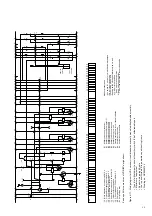
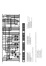
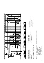
(Figures 4/4, 4/6 and 4/7)
The opening procedure is initiated by mechanical OFF
push-button 12 or by activation of one of releases -Y2,
-Y4, -Y7 or -Y9. Observe the notes in section 4.3.1 on
control of the releases. Release mechanism 31 then
permits drive shaft 30 to be turned further by the spring
energy storage mechanism, which is still sufficiently
charged. Opening spring 27, which is thus released,
moves contact 20.3 into the open position at a defined
speed.
4.4.4
Auto-reclosing sequence
An OFF-ON or OFF-ON-OFF auto-reclosing sequen-
ce is activated and checked by the protection
system. It is necessary for the spiral spring in the
operating mechanism to be in the (re-)charged
condition, with the circuit-breaker in the closed
position. The (re-)charging process is carried out
automatically after closing of the breaker on
breakers with motor charging mechanisms, but
must be carried out manually on breakers without
charging motors (or when the charging motor has
broken down). Opening of the breaker is also
possible during the (re-)charging process, but sub-
sequent closing of the breaker is however blocked
until the charging process has been completed.
4.4.5
Quenching principle of the vacuum interrupter
Due to the extremely low static interrupter cham-
ber pressure of 10
-4
to 10
-8
mbar, only a relatively
small contact gap is required to achieve a high
dielectric strength. The arc is extinguished on one
of the first natural current zeros.
Due to the small contact gap and the high
conductivity of the metal vapour plasma, the arc
drop voltage, and additionally, due to the short
arcing time, the associated arc energy, are extre-
mely low, which has advantageous effects on
the life of the contacts and thus on that of the
vacuum interrupters.
4.5
Interlocks/protection against maloperation
for the withdrawable circuit-breaker part
A series of interlocks are provided to prevent
dangerous situations and any maloperation. The
interlocks of the panel system ZS and/or the
mounting frame, which are normally effective, are
as follows (concerning the circuit-breaker):
• The withdrawable part can only be moved from
the test/disconnected position into the service
position (and back) with the circuit-breaker open
and the earthing switch open (that means that
the breaker must opened before)
• The circuit-breaker can only be closed when the
withdrawable part is precisely in the defined test
position or service position (mechanical inter-
lock, with additional electrical interlock for
circuit-breakers with electrical releases).
• The circuit-breaker can only be opened
manually in the service or test position when no
control voltage is applied, and cannot be closed
(electromechanical interlock).
• Connection and disconnection of the control
wiring plug connector (8.1) is only in the test/
disconnected position possible.
• The earthing switch can only be closed when the
withdrawable part is in the test/disconnected
position or the removed position (mechanical
interlock).
• The withdrawable part cannot be moved from
the test/disconnected position into the service
position when the earthing switch is closed
(mechanical interlock).
• Details of any additional interlocks, e.g. in
connection with a blocking magnet on the
withdrawable part and/or earthing switch
operating mechanism, can be found in the order
documents for each individual case (see also
section 8.5.6).

