


3
1B
Install the bracing for the unit (pipe saddle, direct mount or
pipe driven in the ground). Attach the U-bolts to the 2” pipe
using silicone spray or Teflon tape to prevent galling (see
Figure 1).
2" x 40"
M ounting Pipe
M eter Run
"U" M ounting
Bolt
Saddle
Figure 1. Saddle Mount
1C
Position the enclosure on the 2” mounting pipe, and secure in
place with two U-bolts, flat washers, lock washers and two
9/16” bolts (see Figure 2).
Flat and lock washers
2 " Mounting Pipe
U - Bolt
with 9/16" bolt
Figure 2. Pipe Mounts
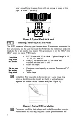
1D
Mount the manifold to the bottom of the unit. The right port of
the unit is normally high pressure (upstream side). Check the
XIMV model number to verify that it is designed for flow from
left to right (4 CYC) or right to left (4 AYC). The user can look
on the transducer for (H or +) for high side and (L or -) for low
side. For direct mount manifolds, the direction is very
important. See Figure 3 for a typical manifold configuration.
1E
Connect the stainless steel tubing from the manifold to the
orifice tap valves. With the manifold equalized to avoid
damaging the transducer, apply pressure to the manifold, and
check for leaks. For the best measurement, use large bore,
Summary of Contents for TOTALFLOW X G4 Series
Page 1: ......


