17
The duration that each parameter is displayed can vary from 1 to 255
seconds (default is 4 seconds); a setting of 0 seconds will turn that
display item off.
Visual Alarm & Status Codes
After the unit completes recording of Log Period flow and operational
records, the LCD will show any alarm conditions that have occurred.
Also, the date, hour and type of alarm conditions are stored in the
device’s memory. Status codes are also displayed when the conditions
exist. An alarm or status code can be a character, letter or symbol. The
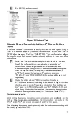
alarm and status codes shown in Table 2 will appear on the right side of
the LCD screen (see Figure 12).
Figure 12. Annunciator Locations
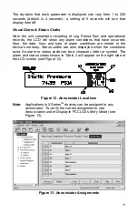
Note:
Applications in XSeries
G4
devices can be assigned to any
annunciator. To verify the current assignments, see
Annunciators
under
Display
in PCCU32’s
Entry Mode
(see
Figure 13).
Figure 13. Annunciator Assignments
Summary of Contents for TOTALFLOW X G4 Series
Page 1: ......


