B0431
Emax X1-Tmax T7-Tmax T8
49/66
Doc N°
Mod.
Apparatus
Scale
Page No
1SDH000587R0002
3.8. Main functions
3.8.1. Watchdog
PR332/P and PR333/P provide certain watchdog functions able to ensure that CB and protection release faults are managed
properly. These functions are as follows:
- Watchdog for presence of Auxiliary power supply with “plug” icon displayed.
- RATING PLUG validity.
- Watchdog for proper connection of the current sensors (CS). If it is enabled, any anomalies are indicated by a special alarm
message and the “alarm” LED coming on, and the circuit-breaker opens after 1s.
- Watchdog for proper connection of the Trip Coil (TC). If it is enabled, any anomalies are indicated by a special alarm message
and the “alarm” LED coming on; if the PR330/D-M module is installed, this activates the coil opening command (YO), thus
opening the CB.
- Watchdog for protection of Hw Trip. If it is enabled, in the event of the sensors being disconnected or a Rating Plug error, a CB
opening command is given by the TC being enabled.
3.8.2. Circuit-breaker state
PR332/P and PR333/P detect the state of the circuit-breaker by means of specific wiring in the CB itself. When the presence of
current is detected with the circuit-breaker “OPEN”, state error is signalled by means of a warning message and the “warning”
led comes on.
3.8.3. Datalogger
PR332/P and PR333/P, powered with Vaux, possess the Datalogger function: this function can be used for storing and saving
the instantaneous values of certain analog measurements (7 analog channels) and digital measurements (64 digital events) in a
capacious data buffer.
The data can be easily downloaded from the unit using the available communication units (internal module PR330/D-M and
external modules BT030-USB, Ekip T&P) and transferred to any personal computer for processing.
The function can be associated with events or states of the protection release or CB, thus allowing the measurements to be
recorded to suit the desired installation requirements.
The function can be very useful for recording if a trip occurs as it facilitates the subsequent failure analysis.
3.8.3.1.
Settings
- All the settings are available in the Settings-Datalogger menu via system bus or test bus, by means of Ekip Connect.
- Function enabling: allows the operator to activate or shut down the function.
- Sampling frequency: frequency selection determines the number of measurement samples as well as the maximum recording time.
- Stop source: the stop source establishes the event to which interruption of measurement storage must be associated.
- Stop delay: used for entering a storage delay.
- Restart and Stop: storage interruption and forced start commands.
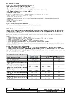
The maximum data recording times depend on the selected frequency and are illustrated in the following table:
Frequency
Recording time
600 Hz
27,3 s
1200 Hz
13,6 s
2400 Hz
6,8 s
4800 Hz
3,4 s
WARNING: Selecting sampling frequency is an important step. In fact, presence of high-order harmonic waves
may cause aliasing on processing of collected data. Use maximum frequency when a harmonic distortion is
available, otherwise data processing may give results which do not match actual system conditions.
ONE one of the following Stop Sources can be selected:
- None
- Any alarm
- L timing
- Any trip
WARNING: If “none” is selected for the Stop Source, the Datalogger can only be stopped by a stop command from the
operator panel, from the system or following a trip generated by the protection release.
B1751

