B0431
Emax X1-Tmax T7-Tmax T8
36/66
Doc N°
Mod.
Apparatus
Scale
Page No
1SDH000587R0002
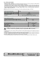
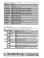
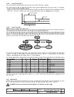
This protection has two states of operation:
State of “WARNING TEMPERATURE” with
–25°C < temp. < -20°C
or
70°C < temp. < 85°C
:
the display is turned off and the “WARNING” LED flashes at 0.5Hz
State of “ALARM TEMPERATURE” with
temp.
≤
–25°C
or
temp.
≥
85°C
: the display is turned off, the “WARNING”
and “ALARM” Leds flash at 2Hz and the Trip is activated (if enabled by means of the “Over Temper. Trip = On” parameter).
In the event of Warning and Alarm, the display is turned off, to preserve its functionality;
The monitored temperature is not visible on the display.
The protection is always active, both with auxiliary supply and in self-supply.
WARNING: If the Trip command of the protection were to be disabled, the protection release would operate,
with the circuit-breaker closed, within a temperature range where correct operation of the protections is not
guaranteed.
3.6.18. Load control function
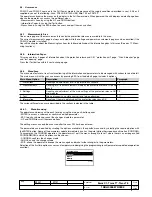
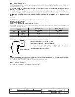
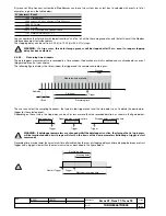
Single loads can be enabled/disabled on the load side before the overload protection L intervenes and trips the circuit-breaker
on the supply side. This is performed by means of contactors or switch-disconnectors controlled by the protection release via
contact S51/P1.
The current thresholds are lower than those available with the protection L, so that the load control can be used to prevent trip-
ping due to overloads. The function is active when an auxiliary power supply is present, or supply from PR330/V (see par. 15.1.4).
The operating logic involves the activation of three contacts when the preset thresholds LC1, LC2 and I
w
are exceeded.
Thresholds LC1 and LC2 are expressed as a percentage of I
1
(current threshold specified for protection L) while the “warning
current” I
w
is expressed as an absolute value. The allowable values are given in the following table:
Threshold LC1
50%...100% x I1 step 1% I1
Threshold LC2
50%...100% x I1 step 1% I1
Threshold Iw
0,3 ...10,0 x In step 0,05 In
Contact S51/P1 can be associated with thresholds LC1 and LC2, and the configuration (NO or NC), delay time and latch settings
can be entered via the protection release.
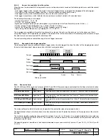
3.6.19. Double protection set
PR333/P allows a second set of protections to be configured.
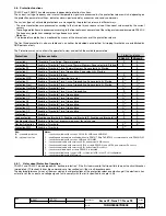
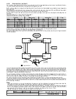
Activation of the “Dual Set“ function in the Settings-Dual set menu allows the operator to configure a second set of all the avail-
able protections, called Set B. The event for automatic set change-over can also be associated in the settings menu.
If Dual Set is enabled, the protections menu will present a new level, where the Set to be viewed or whose parameters must be
edited can be selected. (Set A and Set B)
The operator can switch from set A to set B when there is a change in the network configuration or when there is an emergency
capable of changing the load capacity and short-circuit levels.
The automatic event that can be selected by the user for automatic set change-over can be:
- Change of state of the CB (when there is a change of state from open to closed, the second protection set is activated for a
programmed time). This function also includes adjustment of the time the second set must remain activated after closing. The
main set returns after this time has elapsed).
- Presence of Vaux (the second set of protections activates in the presence of Vaux).
The set can also be edited by the user via the display or by means of a communication module.
3.6.20. Neutral Protection
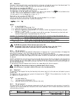
PR332/P and PR333/P allow the current signal of the neutral pole to be processed with different ratios in relation to the value of
the phases. The following values can be set for this protection: I
n
N =Off - 50% - 100% - 150% - 200% * I
n
.
The adjustments can be made via the menu in the Settings-Circuit-breaker-Neutral Protection section.
Regulation of the neutral value (I
n
N) must conform to the following formula: (I
1
x I
n
N)
≤-
Iu.
With four-pole circuit-breakers, the protection release performs the test automatically and transmits a fault signal following failure
to conform to this formula. If the circuit-breaker is the three-pole type with external neutral, no tests will be performed by the
protection release and correction of the settings is at the user’s charge.
E.g.: With CB E1B800 (Iu=800A), Rating plug 400A (In=400A) and I1=1In, the I
n
N setting could be: 50-100--150-200% .
With CB E1B800 (Iu=800A), Rating plug 800A (In=800A) and I1=1In, the I
n
N could be: 50-100%.
The I
1
=1I
n
setting is the maximum setting of the protection against overload. The real permissible maximum setting setting must
take account of derating due to the temperature, the terminals used and the altitude, or In (rating plug)
≤
50% of the size of the
circuit-breaker.
WARNING: In some installations, where particularly high harmonics occur, the current circulating on the neutral
may be higher than that of the phases.
B1751

