


20 CI/FSV/FSS/430/450-EN Rev. G |
VortexMaster FSV430, FSV450 SwirlMaster FSS430, FSS450
5
Installation
DANGER
Danger of explosion if the device is operated with the
transmitter housing or terminal box open!
Before opening the transmitter housing or the terminal box,
note the following points:
— Check that a valid fire permit is available.
— Make sure that there is no explosion hazard.
— Switch off the power supply before opening and observe
a waiting time of t > 20 minutes.
5.1
Installation conditions
5.1.1
General information
A Vortex or Swirl flowmeter can be installed at any point in the
pipeline system. However, the following installation conditions
must be considered:
— Compliance with the ambient conditions
— Compliance with the recommended inlet and outlet
sections.
— The flow direction must correspond to that indicated by
the arrow on the sensor
— Compliance with the required minimum interval for
removing the transmitter and replacing the sensor
— Avoidance of mechanical vibrations of the piping (by fitting
supports if necessary)
— The inside diameter of the sensor and the piping must be
identical
— Avoidance of pressure oscillations in long piping systems
at zero flow by fitting gates at intervals
— Attenuation of alternating (pulsating) flow during piston
pump or compressor conveying by using appropriate
damping devices. The residual pulse must not exceed
10 %. The frequency of the conveying equipment must not
be within the range of the measuring frequency of the
flowmeter.
— Valves / gates should normally be arranged in the flow
direction downstream of the flowmeter (typically: 3 x DN).
If the measuring medium is conveyed through piston /
plunger pumps or compressors (pressures for fluids >
10 bar / 145 psi), it may be subject to hydraulic vibration
in the piping when the valve is closed. If this does occur,
the valve absolutely has to be installed in the flow direction
upstream of the flowmeter. Suitable damping devices (e.g.
air vessels) might need to be fitted.
— When fluids are measured, the sensor must always be
filled with measuring medium and must not run dry.
— When fluids are measured and during damping, there
must be no evidence of cavitation.
— The relationship between the measuring medium and the
ambient temperature must be taken into consideration
(see data sheet).
— At high measuring medium temperatures > 150 °C
(> 302 °F), the sensor must be installed so that the
transmitter or terminal box is pointing to the side or
downward.
5.1.2
Inlet and outlet sections
SwirlMaster FSS430, FSS450
On account of its operating principle, the swirl flowmeter
functions virtually without inlet and outlet sections.
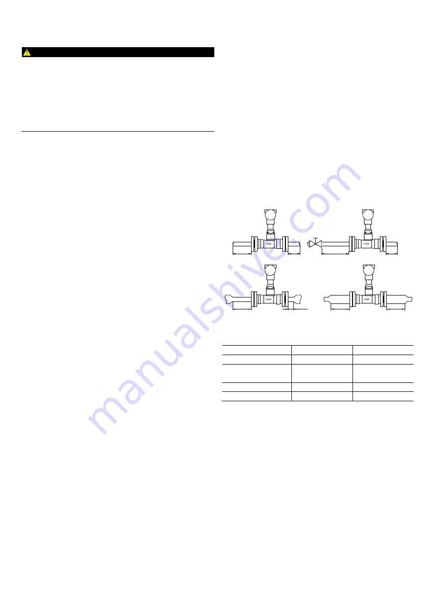
The figures below show the recommended inlet and outlet
sections for various installations.
Fig. 7:
Straight pipe sections
Installation
Inlet section
Outlet section
A
Straight pipe
min. 3 x DN
min. 1 x DN
B
Valve upstream of
the meter tube
min. 5 x DN
min. 1 x DN
C
Pipe reduction
min. 3 x DN
min. 1 x DN
D
Pipe extension
min. 3 x DN
min. 3 x DN
Additional inlet and outlet sections are not required
downstream of reductions with flange transition pieces in
accordance with DIN 28545 (α/2 = 8°).
G11753
≥3 x DN
≥3 x DN
A
B
C
D
≥3 x DN
≥ 1 x DN
≥5 x DN
≥1 x DN
≥3 x DN
≥1 x DN


