11
L1
L2
L3
Uaux
Internal
Relay
Fault
+
-
Motor
Restart
Enable
Startup
Information
from Motor
Thermal
Prior
Alarm
Signal for
T
ripped
Motor
T
rip
Output
Relay
63
62
61
1 A
5 A
1 A
5 A
1 A
5 A
25
26
27
12
3
4
5
6
78
9
1 A
5 A
70
71
72
Rx Tx
65
66
IRF
68
69
77
78
74
75
80
81
10
11
1
1
SGB/1
SGB/2
SGB/7
SGB/8
SGB/3
TRIP
R
SEAL-IN
Σ
>
ts
1
+
B
+
C
+
F
+
E
+
D
+
A
3
SGB/4
S
T
ALL
I/O
I»
Io>
I<
S
T
ART
∆
I
I t
2
REST
A
R
T
INHIBIT
REST
A
R
T
INHIBIT
SGB/5
RELA
Y RESET
θ>θ
i
θ>θ
a
θ>θ
t
SGB/6
EXTERNAL
TRIP
U1 SPCJ 4D34
U3 SPTK 4E3
U2 SPTU _ R2
s
s
BLOCK DIAGRAM WITH F
ACT
ORY
SETTINGS OF SWITCHES SGR
SP
AM 150 C
I
0
–
+
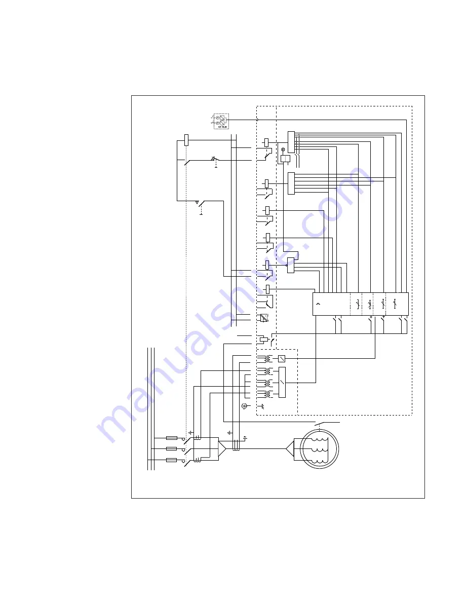
Example 3
Protecting a
direct started
motor with a low
safe stall time
In many applications, e.g. ExE-type drives, the
motor is not allowed to be in a stalled condi-
tion as long as its own start-up time. To find
out whether the motor is speeding up or not, a
speed switch on the motor shaft is used. The
switch should be open at standstill and close
when the motor speeds up.
The speed switch information is used to control
the start-up stress monitor and the setting ts is
set a little shorter than the maximum allowed
jam time t
e
. If the motor starts accelerating, the
speed switch will inhibit the start-up supervision
unit trip and leave the protection to the thermal
unit. If the motor does not speed up, tripping
will be carried out after the time t
s
= t
e
.
The speed switch should be open at standstill and close when the motor speeds up.
Fig. 7. Protection of a directly started motor. A speed switch on the motor is used to produce a
secure stall protection even though the maximum safe stall time of the motor is less than the start-
up time.
Note that because of the fact that only two phase CTs are used, the third phase is reconstructed by
summing the two monitored currents through the third winding.
Summary of Contents for SPAM 150 C
Page 1: ...SPAM 150 C Application examples Technical information ...
Page 23: ...23 ...


