


Section 3
SPA operation principle
3.1
Operation principle
IP14401-1 v3
M11880-3 v2
The SPA bus uses an asynchronous serial communications protocol (1 start bit, 7
data bits + even parity, 1 stop bit) with data transfer rate up to 38400 bit/s. For
more information on recommended baud rate for each type of IED, refer to
Technical reference manual. Messages on the bus consist of ASCII characters.
3.1.1
Introduction of SPA protocol
M11880-7 v2
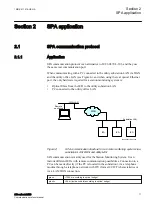
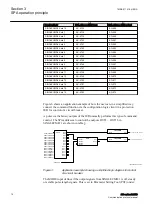
The basic construction of the protocol assumes that the slave has no self-initiated
need to talk to the master but the master is aware of the data contained in the slaves
and, consequently, can request required data. In addition, the master can send data
to the slave. Requesting by the master can be performed either by sequenced
polling (for example, for event information) or only on demand.
The master requests slave information using request messages and sends
information to the slave in write messages. Furthermore, the master can send all
slaves in common a broadcast message containing time or other data. The inactive
state of bus transmit and receive lines is a logical "1".
3.1.2
SPA protocol
M11880-10 v5
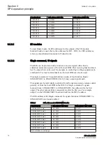
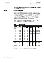
The tables below specify the SPA addresses for reading data from and writing data
to an IED with the SPA communication protocol implemented.
The SPA addresses for the pulse counter values PCFCNT:1 to PCFCNT:16 are
found in table
.
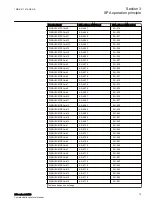
Table 1:
SPA addresses for the PCFCNT function
Function block
SPA address CNT_VAL
SPA address NEW_VAL
PCFCNT:1
6-O-2788
6-O-2787
PCFCNT:2
6-O-2794
6-O-2793
PCFCNT:3
6-O-2800
6-O-2799
PCFCNT:4
6-O-2806
6-O-2805
PCFCNT:5
6-O-2812
6-O-2811
PCFCNT:6
6-O-2818
6-O-2817
PCFCNT:7
6-O-2824
6-O-2823
PCFCNT:8
6-O-2830
6-O-2829
PCFCNT:9
6-O-2836
6-O-2835
Table continues on next page
1MRK 511 418-UEN A
Section 3
SPA operation principle
650 series 2.2 IEC
13
Communication protocol manual


