


2TLC010073M0201 Rev.G
15
A
B
A
4
43
44
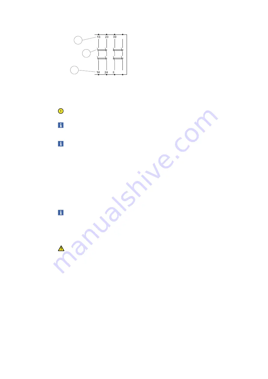
A.
Connectors:
Terminals in connection blocks.
B.
NO contact:
The NO contact is open when the relay is inactivated and closed when the
relay is activated.
Caution!
A relay output is in safe state when the contact is open.
Note!
The NO contact is open at all types of internal failures and is a safe
output.
Note!
Arc suppression for inductive loads is recommended to get a longer
lifetime for the relay contacts.
5.4
Safety device interface
Sentry safety relays have interfaces with inputs/outputs (I/O:s) for connections of safety
devices.
Inputs/Outputs
T1/T2 detect short circuits to +24 VDC or other OSSD signals and are designed for supplying
signals to different types of safety devices.
Note!
It is not necessary to connect T1/T2 to the safety devices. The safety
level may be reduced if T1/T2 are not used. Possible errors in the
connected safety devices and wires may not be identified.
R1/R2 receives the signals from the safety devices.
Warning!
The safety relays and the safety devices supplied with 24 VDC must be
connected to PELV/SELV power supply.
5.5
Test, start and reset interface
The safety relay has an interface for test, start and reset functions. The safety relay enters
inactive mode when at least one input is not accepted. The safety relay enters active mode
when the inputs are accepted, and a reset is performed.
5.6
Automatic reset
When at least one input signal is not accepted, the safety relay enters inactivated mode. The
MODE LED light blue and at least one of CH1/CH2 LED will turn OFF. When the safety input
signals are accepted and the test (X1/X4) circuit is closed, an automatic reset is made. The
relay activates and the three LEDs will light green.