background image

Summary of Contents for Scalable I/O

Page 1: ...ROBOTICS Application manual Scalable I O ...

Page 2: ...Trace back information Workspace 22B version a10 Checked in 2022 06 15 Skribenta version 5 5 019 ...

Page 3: ...Application manual Scalable I O RobotWare 7 7 Document ID 3HAC070208 001 Revision F Copyright 2019 2022 ABB All rights reserved Specifications subject to change without notice ...

Page 4: ...ty by ABB for losses damage to persons or property fitness for a specific purpose or the like In no event shall ABB be liable for incidental or consequential damages arising from use of this manual and products described herein This manual and parts thereof must not be reproduced or copied without ABB s written permission Keep for future reference Additional copies of this manual may be obtained f...

Page 5: ...eneral installation information 41 3 2 Installing digital base devices 45 3 3 Installing safety digital base devices 48 3 4 Installing add on devices 53 3 5 Coil neutralization 55 4 Software commissioning 55 4 1 Information about ABB Scalable I O devices 57 4 2 Connecting the EtherNet IP network 58 4 3 Configuring Scalable I O devices using RobotStudio 69 4 4 Configuring Scalable I O devices using...

Page 6: ...This page is intentionally left blank ...

Page 7: ...d configurations of industrial network hardware software Personnel responsible for I O system configuration System integrators Prerequisites The reader should have the required knowledge of Mechanical installation work Electrical installation work System parameters and how to configure them RobotStudio References Document references Document ID Reference 3HAC032104 001 Operating manual RobotStudio...

Page 8: ...ces added in sections Introduction on page11 Hardware overview on page13 I O device descriptions Status LED descriptions Technical data Inform ation about ABB Scalable I O devices on page 55 and Configuring Scalable I O devices using RobotStudio on page 58 New section Setting up safety digital base devices Updated the section References on page 7 Information about node commissioning for other Ethe...

Page 9: ... New section including information about configuration of Scalable I O devices Software commissioning on page 55 New section including information about prerequisites recommen ded work process and troubleshooting for safety digital base devices Configuring safety digital base devices on page 72 Information about status signal names for safety digital devices added in Information about ABB Scalable...

Page 10: ... of firewalls application of authentication measures encryption of data installation of anti virus programs etc to protect the product the network its system and the interface against any kind of security breaches unauthorized access interference intrusion leakage and or theft of data or information ABB Ltd and its entities are not liable for damage and or loss related to such security breaches an...

Page 11: ...urpose of this Options When using the standard Plug Produce interface no additional RobotWare options or hardware options are required to connect to the robot controller When using the RobotWare options 3024 1 EtherNet IP Scanner and or 3024 2 EtherNet IP Adapter more configuration possibilities are available Device interfaces The add on devices have an optical interface and must be attached to a ...

Page 12: ...ce Compact and scalable Can be mounted inside the controller and or distributed outside Supports standard DIN rail mounting Galvanically isolated add on devices Dual port switch for daisy chaining Fast signal setting with Change of State 12 Application manual Scalable I O 3HAC070208 001 Revision F Copyright 2019 2022 ABB All rights reserved 1 Introduction Continued ...

Page 13: ...re part no Connectors digital base add on 3HAC060919 001 Connectors analog add on 3HAC060925 001 Connectors relay add on 3HAC060926 001 Connectors safety I O 3HAC069538 001 DIN bracket 3HAC062073 001 Note See manufacturer Phoenix for recommendation on conductor connections Communication The digital base device communicates over the EtherNet IP communication protocol to the robot controller or to o...

Page 14: ...device combinations Digital base device with add ons The illustration below shows a combination of a digital base device and connected add on devices Industrial network Digital Base DSQC1030 Digital Add On DSQC1031 Analog Add On DSQC1032 Relay Add On DSQC1033 Relay Add On DSQC1033 Controller Op cal link Op cal link Op cal link Op cal link xx2200000943 Note Up to four add on devices can be controll...

Page 15: ...DSQC1033 Relay Add On DSQC1033 Controller Op cal link Op cal link Op cal link Op cal link xx2200000944 Note Up to four add on devices can be controlled by each safety digital base device with maintained performance and any combination of add on devices is supported Continues on next page Application manual Scalable I O 15 3HAC070208 001 Revision F Copyright 2019 2022 ABB All rights reserved 2 Hard...

Page 16: ...C1033 Controller Op cal link Op cal link Op cal link Op cal link EtherNet xx2200000945 Note Both digital base devices communicate with their connected add ons via an optical interface Communication between the two digital base devices must however be enabled through an EtherNet cable daisy chaining Continues on next page 16 Application manual Scalable I O 3HAC070208 001 Revision F Copyright 2019 2...

Page 17: ...l link Op cal link Op cal link EtherNet Safety Digital Base DSQC1042 Safety Digital Base DSQC1042 xx2200000946 Note The first safety digital base device communicates with the connected add ons via an optical interface Communication between the two safety digital base devices must however be enabled through an EtherNet cable daisy chaining Application manual Scalable I O 17 3HAC070208 001 Revision ...

Page 18: ...herNet X3 Logic power X4 EtherNet X5 i The numbers printings on the module only show the I O numbers digital input output It is not the pin position number for connector X1 or X2 only I O number Connectors Right side description Left side description Connector Location 4 PWR 2 PWR X4 Logic power Top 3 GND 1 GND Continues on next page 18 Application manual Scalable I O 3HAC070208 001 Revision F Cop...

Page 19: ...n i The numbers printings on the module only show the I O numbers digital input output It is not the pin position number for connector X1 or X2 only I O number Technical data Dimensions and weight Note Data Description 75x33 3x101 Dimension Length x Width x Height 117 g Weight Environmental conditions Note Data Description 5 65 C Operating temperature 40 70 C Storage temperature 10 95 non condensi...

Page 20: ...ctive load 10 mF Max capacitive load 1 mm2 Recommended cable area Yes Surge protected Yes Thermal protection 0 5 ms Max delay time Digital inputs Note Data Description 30 5 V Input voltage level Lo 15 30 V Input voltage level Hi 10 V Type switch voltage 0 5 mA Input current level Lo typically 4 mA 2 mA Input current level Hi 30 V Max voltage Yes Reverse polarity protected Yes Surge protected 0 5 m...

Page 21: ...en pressed for more than 10 s The device goes back to the previ ous state RED GREEN flashing Red 100 ms Green 100 ms Red 100 ms The device performs a self test or is in error RED steady MS Module status LED The bicolor green red LED indicates the status of the device It indicates whether or not the device has power and is operating properly The LED is controlled by software The following table sho...

Page 22: ...ication Remedy cause Description LED color LED label Operating at 10 Mbps OFF Speed Operating at 100 Mbps YELLOW steady Remedy cause Description LED color LED label No link is established OFF Link activity Link is established GREEN steady There is activity on this port GREEN flashing Status LEDs at power up The system performs a test of the MS and NS LEDs during startup The purpose of this test is...

Page 23: ... 3 sec The Power LED flashes red two times Factory reset Long press and hold 10 sec CAUTION Use a straightened out paper clip or a similar blunt object to carefully press the reset button Using sharp objects or pressing with force may damage the reset button Note Factory reset can also be made remotely via RobotStudio see Removing and resetting an I O device configuration on page 66 Application ma...

Page 24: ...bout how to set up the safety digital base device and its dual channel signals see Configuring safety digital base devices on page 72 xx2100001681 Description Connector Digital outputs process power X1 Digital inputs X2i EtherNet X3 Logic power X4 EtherNet X5 Connectors Right side description Left side description Connector Location 4 PWR 2 PWR X4 Logic power Top 3 GND 1 GND Continues on next page...

Page 25: ...SDI_12_ 1 SDI_11_ X3 EtherNet X5 EtherNet Down Performance level data Description Type of data Up to Cat 3 CAT according to ISO 13849 1 Up to PL e Performance Level PLr according to ISO 13849 1 In Cat 3 dual channel config 4 29 x 10 8 Cat 3 PFHD Dual channel In 904 years MTTFD Dual channel Out 928 years 90 DCAVG 20 years Service lifetime Technical data Dimensions and weight Note Data Description 7...

Page 26: ...ircuit current 100 uA Leakage current 24 VDC Rated voltage 30 VDC Max voltage 0 5V at 500 mA Max voltage drop max switching repetition rate 10 sec 700 mH Max inductive load 3 3 mF Max capacitive load 1 mm2 Recommended cable area Yes Surge protected Yes Thermal protection 21 ms Max delay time Digital inputs Note Data Description 30 5 V Input voltage level Lo 15 30 V Input voltage level Hi 10 V Type...

Page 27: ...D color The device has no power or is not online OFF The device has not completed the startup The device is in standby state GREEN steady The device is online but has no connections in the established state GREEN flashing The device is booting RED flashing 500 ms ON 500 ms OFF The reset button has been pressed for more than 3 s The device goes back to the previ ous state RED flashing Red 100 ms Th...

Page 28: ...D color The device has no power or is not online OFF The device is online and has connection in the established state GREEN steady The device is idle or in standby state GREEN flashing Abort The device has a recoverable fault RED flashing The device has an unrecoverable fault and may need repla cing RED steady The device is in self test state or the device needs commis sioning due to configuration...

Page 29: ...t button can be used in different ways to reset the device Indication Description Function Regular reset same as tog gling the power Pressed once 3 sec The Power LED flashes red once Resets the IP settings to ABB default values Short press and hold 3 sec The Power LED flashes red two times Factory reset Long press and hold 10 sec CAUTION Use a straightened out paper clip or a similar blunt object ...

Page 30: ...and process power X1 Digital inputs X2 Status LEDs The DSQC1031 device has the following status LEDs Status LED color LED description LED label Digital outputs DO 1 16 Digital inputs DI 1 16 Addressed GREEN steady Power PWR Not addressed GREEN flashing Boot RED flashing Continues on next page 30 Application manual Scalable I O 3HAC070208 001 Revision F Copyright 2019 2022 ABB All rights reserved 2...

Page 31: ...1 DI15 2 DI07 10 DI16 1 DI08 Technical data Dimensions and weight Note Data Description 75x33 3x101 Dimension Length x Width x Height 105 g Weight Environmental conditions Note Data Description 5 65 C Operating temperature 40 70 C Storage temperature 10 95 non condensing Permissible relative humidity IP20 Degree of protection Digital outputs Note Data Description 500 mA Rated current Continues on ...

Page 32: ...0 5 ms Max delay time Digital inputs Note Data Description 30 5 V Input voltage level Lo 15 30 V Input voltage level Hi 10 V Type switch voltage 0 5 mA Input current level Lo typically 4 mA 2 mA Input current level Hi 30 V Max voltage Yes Reverse polarity protected Yes Surge protected 0 5 ms Internal delay time Programmable 0 65 ms Filter time Default value 5 5 ms 32 Application manual Scalable I ...

Page 33: ...nputs and outputs X1 Logic and process power X2 Status LEDs The DSQC1032 device has the following status LEDs Status LED color LED description LED label Addressed GREEN steady Power PWR Not addressed GREEN flashing Boot RED flashing Continues on next page Application manual Scalable I O 33 3HAC070208 001 Revision F Copyright 2019 2022 ABB All rights reserved 2 Hardware overview 2 3 2 Analog add on...

Page 34: ...tion 5 65 C Operating temperature 40 70 C Storage temperature 10 95 non condensing Permissible relative humidity IP20 Degree of protection Analog inputs Note Data Description 0 10 V Input range 12 bits 2 44 mV Resolution 0 5 25 mV Inaccuracy typically 100 kOhm Input impedance Yes Reverse polarity protected Yes Surge protected 2ms Delay time Analog outputs Note Data Description 0 10 V Output range ...

Page 35: ...racy 1 kOhm Min load impedance Yes Surge protected Yes Short circuit protection 2 ms Delay time Application manual Scalable I O 35 3HAC070208 001 Revision F Copyright 2019 2022 ABB All rights reserved 2 Hardware overview 2 3 2 Analog add on device DSQC1032 Continued ...

Page 36: ...2 Logic and process power X3 Status LEDs The DSQC1031 device has the following status LEDs Status LED color LED description LED label Relay outputs RO 1 8 Digital inputs DI 1 8 Addressed GREEN steady Power PWR Not addressed GREEN flashing Boot RED flashing Continues on next page 36 Application manual Scalable I O 3HAC070208 001 Revision F Copyright 2019 2022 ABB All rights reserved 2 Hardware over...

Page 37: ... weight Note Data Description 75x33 3x101 Dimension Length x Width x Height 133 g Weight Environmental conditions Note Data Description 5 65 C Operating temperature 40 70 C Storage temperature 10 95 non condensing Permissible relative humidity IP20 Degree of protection Relay outputs Note Data Description 230 VAC Max switching voltage 2 A Max switching current Reinforced Isolation Application manua...

Page 38: ...This page is intentionally left blank ...

Page 39: ...rmal air convention The individual devices must be mounted side by side on the DIN rail starting with the digital base device The add on devices are placed to the right of the digital base device xx1600002032 Continues on next page Application manual Scalable I O 39 3HAC070208 001 Revision F Copyright 2019 2022 ABB All rights reserved 3 Hardware installation 3 1 General installation information ...

Page 40: ...e mounted horizontally xx2200000942 Note To ensure that the maximum operating ambient temperature is not exceeded a minimum of 30 mm space is recommended between the system and other components 40 Application manual Scalable I O 3HAC070208 001 Revision F Copyright 2019 2022 ABB All rights reserved 3 Hardware installation 3 1 General installation information Continued ...

Page 41: ... scanner to any of the con nectors X3 or X5 3 For information about the pinout see Connectors on page 18 Connect the logic power supply to connector X4 4 CAUTION The process power supply must be supplied separately Connecting the process power supply through the logical power supply connector may damage the device Connect process power supply and GND to the input and output connectors X1 and X2 No...

Page 42: ...e that the main power has been switched off 1 Disconnect all connectors 2 xx1700000276 Press the DIN bracket gently to the left and pull the device straight out 3 xx1600002039 Snap off the DIN bracket and refit it to the re moved device 4 Continues on next page 42 Application manual Scalable I O 3HAC070208 001 Revision F Copyright 2019 2022 ABB All rights reserved 3 Hardware installation 3 2 Insta...

Page 43: ...00000276 Press the DIN bracket gently to the left and pull the device straight out Leave the DIN bracket attached to the rail 3 xx1600002039 Remove the DIN bracket from the new device 4 Continues on next page Application manual Scalable I O 43 3HAC070208 001 Revision F Copyright 2019 2022 ABB All rights reserved 3 Hardware installation 3 2 Installing digital base devices Continued ...

Page 44: ... any of the connectors X3 or X5 on the previous base device The logical power supply connector X4 of up to five base devices in total can be connected in parallel if the devices are placed inside the same controller cabinet i e over short distances For all other applications the logical power must be supplied separately to each base device The process power supply must always be supplied separatel...

Page 45: ...042 are installed in the same way as the digital base devices See Installing digital base devices on page 41 Continues on next page Application manual Scalable I O 45 3HAC070208 001 Revision F Copyright 2019 2022 ABB All rights reserved 3 Hardware installation 3 3 Installing safety digital base devices ...

Page 46: ..._2_ SDO_2_ SDI_2_ SDI_2_ SDI_3_ SDI_3_ SDI_4_ SDI_4_ Safety controller Industrial network GND GND GND GND Sensor GND Output GND Output xx2200000441 Safety digital base device used as dual channel safety output Safe I O 24V_IN GND GND SDO_1_ SDO_2_ STO_1 STO_2 GND Safety controller Industrial network GND GND Inverter DC AC M xx2200000566 Continues on next page 46 Application manual Scalable I O 3HA...

Page 47: ...elay can be increased Safe I O OSSD test pulses SDI_1 GND OUT GND OUT GND SDI_2 GND Safety controller Industrial network Safety device GND GND GND GND xx2200000938 Values Remarks Configuration element Increasing this parameters will extend the time required for the SDI to switch from On to Off Safety Input X On_Off Delay 2 input no dependency on test out Safety Input X Input channel Mode Applicati...

Page 48: ...d to detect the add on device Unpowered add on devices shall be placed last i e to the right otherwise the optical link is broken Note Add ons can also be attached to a safety digital base See Examples of device combinations on page 14 xx1600002032 Installing add on devices Note Action DANGER Before commencing any work inside the cabinet make sure that the main power has been switched off 1 Contin...

Page 49: ...r the last device accord ing to the arrows Press the add on device until it snaps onto the mounting rail 3 Note If the device is not correctly inser ted there is a risk that the optical communication between the devices does not work Continues on next page Application manual Scalable I O 49 3HAC070208 001 Revision F Copyright 2019 2022 ABB All rights reserved 3 Hardware installation 3 4 Installing...

Page 50: ...her add on may damage the devices Connect wires to the inputs and outputs as re quired 5 Configure the device see Configuring an I O device on page 58 6 Removing add on devices Note Action DANGER Before commencing any work inside the cabinet make sure that the main power has been switched off 1 Disconnect all connectors 2 Continues on next page 50 Application manual Scalable I O 3HAC070208 001 Rev...

Page 51: ...ommencing any work inside the cabinet make sure that the main power has been switched off 1 Disconnect all connectors 2 xx1600002037 Press the DIN bracket gently to the left and pull the device straight out Leave the DIN bracket attached to the rail 3 Continues on next page Application manual Scalable I O 51 3HAC070208 001 Revision F Copyright 2019 2022 ABB All rights reserved 3 Hardware installat...

Page 52: ...ket Note The device must be updated if the order is changed see Updating an existing I O device on page 60 6 Note If the device is not correctly inser ted there is a risk that the optical communication between the devices does not work Reconnect all connectors 7 Fit the spare DIN bracket to the removed device 8 52 Application manual Scalable I O 3HAC070208 001 Revision F Copyright 2019 2022 ABB Al...

Page 53: ...s lengthens the life of the switches that control them Clamping with a diode The diode should be dimensioned for the same current as the relay coil and a voltage of twice the supply voltage 24 V DC 0 V xx0100000163 Clamping with a varistor The varistor should be dimensioned for the same current as the relay coil and a voltage of twice the supply voltage xx0100000164 Clamping with an RC circuit R 1...

Page 54: ...This page is intentionally left blank ...

Page 55: ...x utility service ioconfig EDS Behavior ABB Scalable I O devices support both Cyclic and Change of State COS I O connection It is possible to set output signals with a Change of State connection Note Change of State is used together with the parameter production inhibit timer The parameter defines the highest frequency for which a signal change can occur with Change of State Note The Change of Sta...

Page 56: ...ng structure Example Format ABBIO_0_DO3 or ABBIO_0_DI5 or ABBIO_3_RO1 Name of device_slot num ber_type index Status signal names Status signal names for the safety digital base devices are generated according to the following structure Example Format ABBIO_0_DO_Status Name of device_slot num ber_type_Status ABBIO_0_DI_Status 56 Application manual Scalable I O 3HAC070208 001 Revision F Copyright 20...

Page 57: ... Network to gain the advantages with Plug Produce When using the RobotWare options 3024 1 EtherNet IP Scanner or 3024 2 EtherNet IP Adapter more configuration possibilities are available For more information see Application manual EtherNet IP Scanner Adapter For more information about network connections on OmniCore see Operating manual Integrator s guide OmniCore Application manual Scalable I O 5...

Page 58: ... and to replace an I O device with another Configuring an I O device When a base I O device and an add on I O device are connected to the controller they must be configured This procedure describes how to configure the base I O device and add on I O device at the same time However if more add on I O devices should be attached after the first configuration of the base I O device use the Updating an...

Page 59: ...elds Configure as new device Enter the name of the I O device Note The name will be stored in the I O device and will be used for identification and addressing Continues on next page Application manual Scalable I O 59 3HAC070208 001 Revision F Copyright 2019 2022 ABB All rights reserved 4 Software commissioning 4 3 Configuring Scalable I O devices using RobotStudio Continued ...

Page 60: ...evices from the right side of the base I O device otherwise the optical link is broken The update function can also be used for the generation of default signals on a device 1 Start RobotStudio and connect to the OmniCore controller Request write access 2 The add on I O device is attached or removed from the base module The modified I O device appears xx2100000078 3 Right click the modified I O de...

Page 61: ...dated Create new I O signals using name prefix Enter the signal prefix to be used in signal names Not mandatory Note If this field is left empty no signals will be added to the configuration Select OK The I O device is updated Continues on next page Application manual Scalable I O 61 3HAC070208 001 Revision F Copyright 2019 2022 ABB All rights reserved 4 Software commissioning 4 3 Configuring Scal...

Page 62: ...d connect to the OmniCore controller Request write access 2 A new I O device is connected to the private network The detected I O device appears xx2100000082 3 Right click the new I O device and select Configure Or In the I O System tree right click the new I O device and select Configure Device Continues on next page 62 Application manual Scalable I O 3HAC070208 001 Revision F Copyright 2019 2022...

Page 63: ...ame prefix Enter the signal prefix to be used in signal names Not mandatory Note If this field is left empty no signals will be added to the configuration Select OK The I O device is updated 5 Restart the controller Note If a faulty add on I O device is replaced with another add on I O device of the same type there is no need to update the configuration of the base I O device Continues on next pag...

Page 64: ... I O device using the simulated device configuration 1 Start RobotStudio and connect to the OmniCore controller Request write access 2 A new I O device is connected to the private network The detected I O device appears xx2100000084 3 Right click the new I O device and select Configure Or In the I O System tree right click the new I O device and select Configure Device Continues on next page 64 Ap...

Page 65: ...existing I O device MY_PRELOADED_DEVICE Create new I O signals using name prefix Enter the signal prefix to be used in signal names Not mandatory Note If this field is left empty no signals will be added to the configuration Select OK The new I O device will inherit the configuration of the selected device 5 Restart the controller Continues on next page Application manual Scalable I O 65 3HAC07020...

Page 66: ...he OmniCore controller Request write access 2 In the I O System tree right click the I O device to be removed and select Remove Configuration xx2100000086 Continues on next page 66 Application manual Scalable I O 3HAC070208 001 Revision F Copyright 2019 2022 ABB All rights reserved 4 Software commissioning 4 3 Configuring Scalable I O devices using RobotStudio Continued ...

Page 67: ...is important to identify the physical I O device for any device update signal connection or troubleshooting 1 Start RobotStudio and connect to the OmniCore controller Request write access Continues on next page Application manual Scalable I O 67 3HAC070208 001 Revision F Copyright 2019 2022 ABB All rights reserved 4 Software commissioning 4 3 Configuring Scalable I O devices using RobotStudio Cont...

Page 68: ...cal base I O device flashes to identify the I O device in the controller Note For DSQC1042 Safety digital base only the PWR Power LED flashes to identify the I O device in the controller 68 Application manual Scalable I O 3HAC070208 001 Revision F Copyright 2019 2022 ABB All rights reserved 4 Software commissioning 4 3 Configuring Scalable I O devices using RobotStudio Continued ...

Page 69: ...devices cannot be configured using the FlexPendant Configuring an I O device When a base I O device and an add on I O device are connected to the controller these must be configured Use this procedure to configure a new I O device on the FlexPendant 1 Start the FlexPendant and connect to the OmniCore controller 2 On the start screen tap I O and then select I O Devices from the menu 3 Select the I ...

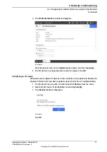
Page 70: ...ed the I O configuration of the base I O device must be updated Note Always attach or remove I O devices from the right side of the base I O device otherwise the optical link is broken 1 On the start screen tap I O and then select I O Devices from the menu 2 Select the I O device to be updated and and tap Configure Continues on next page 70 Application manual Scalable I O 3HAC070208 001 Revision F...

Page 71: ...nt to identify the physical I O device for any device update signal connection or troubleshooting 1 On the start screen tap I O and then select I O Devices from the menu 2 Select the I O device to be identified and and tap Identify 3 The Identify window is displayed xx2100000097 Tap OK Application manual Scalable I O 71 3HAC070208 001 Revision F Copyright 2019 2022 ABB All rights reserved 4 Softwa...

Page 72: ...on page 73 and Application manual Functional safety and SafeMove for instructions on how to define logic diagrams Verify the parameters in the ABB Safety Configuration Report see Verifying parameters in the ABB Safety Configuration Report on page 74 When the set up and configuration is done see Application manual Functional safety and SafeMove for instructions on how to work with the safety config...

Page 73: ...ut signal both signals in the pair must be set to high in the safety controller This is defined with CL copy logic See Application manual Functional safety and SafeMove for instructions on how to define logic diagrams Intput signals There are six dual channel pairs for input signals The twelve input signals are paired in the following way DSQC1042 Dual channel pair SDI_1_ 1 CH1 SDI_1_ SDI_2_ SDI_2...

Page 74: ...dentifier Check sum is a constant that is written in the safety configuration when the button Configure is pressed scid nodeId C0A87D84 The IP address of the device defined in hexdecimal form This is the IP address that is visible in the configuration nodeId snn 5Afe12345678 The Safety Network Number is a constant number for the private network of all con trollers snn scidDateTime 2021 08 12T17 02...

Page 75: ...ual output channel pair will go to ALARM if the outputs for the two signals from the controller originator differ from each other without any discrepancy delay The status will automatically be set to 1 OK when the following is true the Safety Input Latch Error Time 1000 ms has elapsed both inputs outputs have been cleared the cause for the failure has been removed Check cables If the status signal...

Page 76: ...eactivate 3 Start RobotStudio and connect to the OmniCore controller 4 Request write access 5 In the I O System tree right click the target I O device and select Upgrade xx1900001181 6 The Firmware Upgrade Local I O Device window is displayed Note The Firmware location field displays the default firmware file To select a new firmware file click the button and browse to the folder with the new firm...

Page 77: ...dd ons 1 Set the OmniCore controller in manual mode 2 On the start screen tap I O and then select I O Devices from the menu 3 If the I O device is in the running state select the device and and tap Deactivate 4 Select the I O device and and tap Firmware Update Note Firmware upgrade is not possible if the state of the selected I O device is Running Continues on next page Application manual Scalable...

Page 78: ... Browse 6 Tap Upgrade The firmware is upgraded and a message is displayed Note The Upgrade button is enabled only if a new version is detected either in the default firmware path or in a browsed path 78 Application manual Scalable I O 3HAC070208 001 Revision F Copyright 2019 2022 ABB All rights reserved 4 Software commissioning 4 6 Firmware upgrade Continued ...

Page 79: ...ndustrial network EtherNet IP 55 installing add on device 48 installing digital base device 41 installing safety digital base devices 45 L LED module status 21 28 network status 22 28 power 21 27 30 33 36 test run 22 29 N network security 10 P Plug Produce 11 R removing I O device 66 replacing I O device 62 64 S Scalable I O 11 U updating existing I O device 60 upgrade firmware 76 Application manu...

Page 80: ......

Page 81: ......

Page 82: ...7 22 87 2000 ABB Engineering Shanghai Ltd Robotics Discrete Automation No 4528 Kangxin Highway PuDong New District SHANGHAI 201319 China Telephone 86 21 6105 6666 ABB Inc Robotics Discrete Automation 1250 Brown Road Auburn Hills MI 48326 USA Telephone 1 248 391 9000 abb com robotics 3HAC070208 001 Rev F en Copyright 2019 2022 ABB All rights reserved Specifications subject to change without notice ...

Reviews: