background image

Transformer Terminal

RET 541, RET 543, RET 545

1MRS755543

36

Modbus RTU/ASCII

bit rates

300, 600, 1200, 2400, 4800, 
9600, 19200 bps

data bits

5, 6, 7, 8

stop bits

1, 2

parity

none, odd, even

Table 19: General

Toolboxes

CAP 501 
CAP 505 
LNT 505

Event recording

all events are recorded in higher level syntax: 
reason, time, date  
the last 100 events are recorded

Data recording

records operate values

Protection functions 
Control functions 
Condition monitoring functions 
Measurement functions

see Technical Descriptions of Functions, CD-ROM 
(1MRS 750889-MCD)

Self-supervision

RAMs 
ROMs 
EEPROMs 
all analog reference voltages 
automatic test sequences for I/Os and HMI modules 
output contact condition monitoring (all contacts)

Mechanical dimensions

Width: 223.7 mm (1/2 of a 19” rack) 
Height, frame: 265.9 mm (6U) 
Height, box: 249.8 mm 
Depth: 235 mm 
External display module

Width: 223.7 mm 
Height: 265.9 mm 
Depth: 74 mm

Weight of the unit

~8 kg

Table 18: Data communication

Summary of Contents for RET 541

Page 1: ...Transformer Terminal Product Guide RET 541 RET 543 RET 545 ...

Page 2: ......

Page 3: ...ional overcurrent and earth fault overfrequency underfrequency and underimpedance line back up protection Large graphic display either integrated or as an external module Control functions including local and remote control of switching objects includ ing object status indication and interlock ings on bay and substation level Optional automatic on load tap changer control function for single or pa...

Page 4: ...ormers with Master Follower Negative Reactance or Minimizing Circulating Current principles A special control version terminal with volt age regulator and control functions can be applied when integration of voltage regula tion and protection is not allowed The graphical configuration tool based on the IEC 61131 3 standard enables easy cre ation of application specific configurations and MIMIC pic...

Page 5: ... cate the position of switching devices via the MIMIC picture and to control them locally The control function blocks are documented on the CD ROM Technical Descriptions of Functions 1MRS750889 MCD Condition monitoring functions The condition monitoring function blocks are documented on the CD ROM Technical Descriptions of Functions 1MRS750889 MCD General functions Additional functions are availab...

Page 6: ... the transformer termi nals are voltage controlled and optically iso lated with three treshold voltages defined by the order see chapter Ordering The func tion of a digital input can be inverted The programmable filter time removes debounces and short disturbances on a digital input The filter time can be set for each digital input separately Some specific digital inputs can be pro grammed to oper...

Page 7: ... module requires a separate voltage supply from a common source with the main unit The display con sists of 19 rows divided into two windows a main window 17 rows and an assisting win dow 2 rows The graphic display presents detailed infor mation on MIMIC objects events measure ments control alarms and parameters The assisting window is used for terminal depen dent indications alarms and help messa...

Page 8: ...c terminal pro tection and logic function blocks control and measurement functions timers and other functional elements included in the logic functions category The programmable system of RET 54_ trans former terminals allows the output contacts to be operated in accordance with the state of the logic inputs and the outputs of the protec tion control measurement and condition monitoring functions ...

Page 9: ...back type dc dc converter A green protection LED indicator on the front panel is lit when the power supply module is in operation Power supply modules There are two basic types of power supply modules available for the RET 54_ type PS1 _ and type PS2 _ The operating range of digital inputs depends on the type of the power supply module See Technical data Terminal connections All external circuits ...

Page 10: ...O4 PS1_4_TempAlarm 3 4 5 6 7 9 8 10 12 11 13 15 14 16 18 17 1 2 4 5 6 7 X4 2 PS1_4_BI1 PS1_4_BI3 PS1_4_BI2 1 2 3 4 5 6 7 8 9 10 11 12 13 14 15 16 17 18 X5 1 1 2 X5 2 BIO1_5_BI1 BIO1_5_BI11 BIO1_5_BI9 BIO1_5_BI8 BIO1_5_BI7 BIO1_5_BI6 BIO1_5_BI5 BIO1_5_BI4 BIO1_5_BI3 BIO1_5_BI2 BIO1_5_BI10 BIO1_5_BI12 BIO1_5_SO1 BIO1_5_SO2 BIO1_5_SO3 BIO1_5_SO4 BIO1_5_SO5 BIO1_5_SO6 X5 2 PS1_4_ACFail X3 2 1A 5A 1A 5...

Page 11: ...8 BIO1_5_BI7 BIO1_5_BI6 BIO1_5_BI5 BIO1_5_BI4 BIO1_5_BI3 BIO1_5_BI2 BIO1_5_BI10 BIO1_5_BI12 BIO1_5_SO1 BIO1_5_SO2 BIO1_5_SO3 BIO1_5_SO4 BIO1_5_SO5 BIO1_5_SO6 X5 2 PS1_4_ACFail X3 2 1A 5A 1A 5A 1A 5A 17 18 X7 1 X7 1 10 11 12 13 14 15 16 4 5 6 7 8 9 1 2 3 X7 2 5 6 7 8 9 10 13 14 15 16 11 12 1 2 3 4 17 18 BIO2_7_BI9 BIO2_7_BI8 BIO2_7_BI7 BIO2_7_BI6 BIO2_7_BI5 BIO2_7_BI4 BIO2_7_BI3 BIO2_7_BI2 BIO2_7_B...

Page 12: ...I9 BIO2_7_BI8 BIO2_7_BI7 BIO2_7_BI6 BIO2_7_BI5 BIO2_7_BI4 BIO2_7_BI3 BIO2_7_BI2 BIO2_7_BI10 BIO2_7_BI1 BIO1_6_BI1 BIO1_6_BI11 BIO1_6_BI9 BIO1_6_BI8 BIO1_6_BI7 BIO1_6_BI6 BIO1_6_BI5 BIO1_6_BI4 BIO1_6_BI3 BIO1_6_BI2 BIO1_6_BI10 BIO1_6_BI12 PS2_4_HSPO7 PS2_4_HSPO6 8 7 5 6 4 3 1 2 RET 545 3 4 5 6 7 9 8 10 12 11 13 15 14 16 18 17 BIO1_5_SO1 BIO1_5_SO2 BIO1_5_SO3 BIO1_5_SO4 BIO1_5_SO5 BIO1_5_SO6 X5 2 17...

Page 13: ... USINT UINT UDINT SINT REAL INT DWORD DINT BYTE BOOL2INT Type conversion from BOOL inputs to INT output BYTE_TO_ Type conversion from BYTE to WORD DWORD COMH Hysteresis comparator COS Cosine in radians CTD Down counter CTUD Up down counter CTU Up counter DATE_TO_UDINT Type conversion from DATE to UDINT DINT_TO_ Type conversion from DINT to SINT REAL INT DIV Divider DWORD_TO_ Type conversion from D...

Page 14: ...elay timer TON On delay timer TP Pulse TRUNC_REAL_TO Truncation toward zero from REAL to DINT INT SINT UDINT UINT USINT UDINT_TO_ Type conversion from UDINT to USINT UINT REAL UINT_TO_ Type conversion from UINT to USINT UDINT REAL BOOL USINT_TO_ Type conversion from USINT to UINT UDINT REAL WORD_TO_ Type conversion from WORD to DWORD BYTE Table 3 Conditioning monitoring functions available for the...

Page 15: ...ng device 5 indication COIND6 Switching device 6 indication COIND7 Switching device 7 indication COIND8 Switching device 8 indication COLOCAT Logic controlled control position selector COLTC On load tap changer controller voltage regulator COSW1 On off switch 1 COSW2 On off switch 2 COSW3 On off switch 3 COSW4 On off switch 4 MMIALAR1 Alarm channel 1 LED indicator MMIALAR2 Alarm channel 2 LED indi...

Page 16: ...curacies voltage measurement operation time DT mode operation time IDMT mode lower and raise output pulse duration Depends on the frequency of the voltage measured f fn 0 95 1 05 1 0 of the set value or 0 01xUn 1 of the set value or 250 ms 250ms and an inaccuracy which occurs when voltage varies 0 5 100 ms Reset ratio hysteresis 20 of the set Bandwith Table 6 Measurement function blocks General me...

Page 17: ...ension 0 100 0 00 40 00 x In 0 00 40 00 x In 0 00 40 00 x In 0 00 2 00 x Un 0 00 2 00 x Un 0 00 2 00 x Un 0 00 2 00 x Un 0 00 40 00 x In 0 00 2 00 x Un 0 00 2 00 x Un 0 000 60 000 s The recording can be triggered by any or several of the alternatives listed below triggering on the rising or falling edge of any or several of the digital inputs triggering on overcurrent overvoltage or undervoltage m...

Page 18: ...99999 kvarh Residual voltage measurement MEVO1A and MEVO1B Uo Uo 0 150000 V 0 0 120 0 Un Three phase voltage measurement MEVO3A and MEVO3B UL1_U12 UL2_U23 UL3_U31 UL1_U12 UL2_U23 UL3_U31 UL1_U12 average UL2_U23 average UL3_U31 average UL1_U12 average UL2_U23 average UL3_U31 average 0 00 999 99 kV 0 00 999 99 kV 0 00 999 99 kV 0 00 2 00 x Un 0 00 2 00 x Un 0 00 2 00 x Un 0 00 999 99 kV 0 00 999 99 ...

Page 19: ...pply when f fn 0 95 1 05 2 5 of set value or 0 01 x In 2 0 x start current 32 ms 40 ms 40 1000 ms depends on the minimum pulse width set for the trip output 0 95 45 ms 2 of set value or 20 ms Class index E 5 0 or 20 ms Three phase non directional overcurrent protection high set stage NOC3High 3I and instantaneous stage NOC3Inst 3I Start current Operate time Operation mode Measuring mode Drop off t...

Page 20: ... Note The values below apply when f fn 0 95 1 05 0 1 10 x In 2 5 of set value or 0 01 x In 10 40 x In 5 0 of set value 2 5 of measured voltage or 0 01 x Un 2 2 0 x start current 42 ms 50 ms 40 1000 ms depends on the minimum pulse width set for the trip output 0 95 45 ms 2 of set value or 20 ms Class index E 5 0 or 20 ms Transformer Terminal RET 541 RET 543 RET 545 1MRS755543 20 Three phase directi...

Page 21: ...rdation time Operate time accuracy Note The values below apply when f fn 0 95 1 05 3 0 of set value or 0 02 p u 0 50 x Z setting 42 ms 50 ms 70 1030 ms depends on the minimum pulse width set for the TRIP output Typ 1 03 45 ms 2 of set value or 20 ms Stabilized and instantaneous differential protection for transformers Diff6T 3 3 Basic setting the lowest ratio of differential and nominal current to...

Page 22: ...art current 32 ms 40 ms 40 1000 ms depends on the minimum pulse width set for the trip output 0 95 45 ms 2 of set value or 20 ms Class index E 5 0 or 20 ms Non directional earth fault protection high set stage NEF1High I0 and instantaneous stage NEF1Inst I0 Start current Operate time Operation mode Measuring mode Drop off time of the operate time counter 0 10 12 00 x In 0 05 300 00 s Not in use De...

Page 23: ...n directional Uo Forward Reverse 90 60 30 0 IoSin IoCos Not active Active Peak to peak Fundamental frequency 0 1000 ms Operation accuracy Start time Injected neutral current and residual voltage internal time total time Reset time Reset ratio typically Retardation time Operate time accuracy at DT mode Accuracy class index E at IDMT mode Note The values below apply when f fn 0 95 1 05 2 5 of set va...

Page 24: ...acy at DT mode Note The values below apply when f fn 0 95 1 05 2 5 of set value 0 0005 x In 2 5 of set value or 0 01 x Un Phase angle 2 Injected neutral current 2 0 x start current and residual voltage 2 0 x start voltage 72 ms 80 ms 40 1000 ms depends on the minimum pulse width set for the trip output 0 95 50 ms 2 of set value or 20 ms High impedance based restricted earth fault protection REF1A ...

Page 25: ... ms depends on the minimum pulse width set for the trip output 0 98 0 90 0 98 50 ms 2 of set value or 20 ms Residual overvoltage protection low set stage ROV1Low U0 Start voltage Operate time Operation mode Measuring mode 2 0 20 0 of Un 0 05 300 00 s Not in use Definite time Peak to peak Fundamental frequency Operation accuracy Start time injected voltages internal time total time Reset time Reset...

Page 26: ...njected voltages internal time total time Reset time Reset ratio typically Retardation time Operate time accuracy at DT mode Note The values below apply when f fn 0 95 1 05 2 5 of set value or 0 01 x Un 2 x start voltage 32 ms 40 ms 40 1000 ms depends on the minimum pulse width set for the trip output 0 95 Total time for blocking 25 ms Total time when voltage drops below start value 50 ms 2 of set...

Page 27: ...or stator Long time constant for stator Weighting factor of the short time constant for stator Temperature rise of stator at rated current Maximum temperature of stator Short time constant for rotor Long time constant for rotor Weighting factor of the short time constant for rotor Temperature rise of rotor at rated current Maximum temperature of rotor 0 0 999 0 min 0 0 999 0 min 0 00 1 00 0 0 350 ...

Page 28: ...ow apply when f fn 0 95 1 05 2 5 of set value or 0 01 x In 2 00 x start value 32 ms 40 ms 70 1030 ms depends on the minimum pulse width set for the trip output 0 96 45 ms 2 of set value or 20 ms 2 of the calculated ideal operate time or 20 ms Three phase overvoltage protection low set stage OV3Low 3U Start voltage Operate time Time multiplier Operation mode Measuring mode Operation hysteresis 0 10...

Page 29: ... ms 2 of set value or 20 ms Three phase undervoltage protection low set stage UV3Low 3U Start voltage Operate time Time multiplier Operation mode Measuring mode Operation hysteresis 0 10 1 20 x Un 0 1 300 0 s 0 1 1 0 Not in use Definite time C curve Phase to phase voltages peak to peak measurement Phase to phase voltages fundamental freq measurement Phase to earth voltages fundamental freq measure...

Page 30: ...ue U1 Start value U1 Operate time U2 Operate time U1 Operate time U1 Operation mode Rotation direction selection 0 01 1 00 x Un 0 01 1 20 x Un 0 80 1 60 x Un 0 04 60 00 s 0 04 60 00 s 0 04 60 00 s Not in use U1 U2 U1 U1 U2 U2 U1 U1 U1 U2 U1 U1 Forward Reverse Input ROT_DIR Operation accuracy Trip time U2 operation Injected negative sequency voltage internal time total time Trip time U1 operation i...

Page 31: ...ds on the minimum pulse width set for the trip output 2 of set value or 30 ms Overexcitation protection low set stage OE1Low U f and high set stage OE1High U f U f start DT mode U f start IDMT mode U max cont Operate time k Maximum time Constant delay Cooling time Operation mode 1 00 2 00 x U f 1 00 2 00 x U f 0 80 1 60 x Un 0 10 600 00 s 0 1 100 0 500 10000 s 0 1 120 0 s 5 10000 s Not in use Defi...

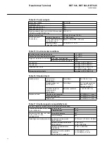
Page 32: ...l is 10 ms 20 ms within the same task 0 8 0 96 1 04 1 2 Table 8 Energizing inputs Rated frequency 50 0 60 0 Hz Current inputs rated current 1 A 5 A thermal withstand capability continuously 4 A 20 A for 1 s 100 A 500 A dynamic current withstand half wave value 250 A 1250 A input impedance 100 m 20 m Voltage inputs rated voltage parameterization 100 V 110 V 115 V 120 V voltage withstand continuousl...

Page 33: ... TCR 0 00618 10 Copper TCR 0 00427 120 Nickel TCR 0 00672 MIL T 24388C Max lead resistance three wire measurement 200 per lead Accuracy 0 5 of full scale 1 0 of full scale for 10 Copper RTD Isolation 2 kV inputs to outputs and inputs to protective earth Sampling frequency 5 Hz Response time Filter time 30 ms 430 ms 5 03 s RTD Resistance sensing current max 4 2 mA RMS 6 2 mA RMS for 10 Copper Curre...

Page 34: ...ture tests according to IEC 60068 2 48 Table 16 Standard tests Insulation tests Dielectric test IEC 60255 5 Test voltage 2 kV 50 Hz 1 min Impulse voltage test IEC 60255 5 Test voltage 5 kV unipolar impulses waveform 1 2 50 s source energy 0 5 J Insulation resistance measurements IEC 60255 5 Insulation resistance 100 M 500 V dc Mechanical tests Vibration tests sinusoidal IEC 60255 21 1 class I Shoc...

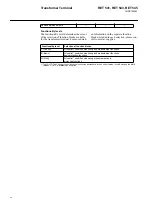
Page 35: ...ol SPA IEC_103 RS 485 connection the RS 485 interface module RER 133 for DNP 3 0 and Modbus protocol DNP 3 0 Modbus data transfer rates DNP 3 0 and Modbus 300 bps 19 2 kbps selectable Rear interface connector X3 3 RS 485 connection LON bus or SPA bus selectable the fibre optic interface module RER 103 is needed for galvanic isolation data transfer rates SPA bus 4 8 9 6 19 2 kbps LON bus 78 0 kbps ...

Page 36: ... operate values Protection functions Control functions Condition monitoring functions Measurement functions see Technical Descriptions of Functions CD ROM 1MRS 750889 MCD Self supervision RAMs ROMs EEPROMs all analog reference voltages automatic test sequences for I Os and HMI modules output contact condition monitoring all contacts Mechanical dimensions Width 223 7 mm 1 2 of a 19 rack Height fram...

Page 37: ...0 V DC B power supply PS1 240 V High or PS2 240 V Ur 110 120 220 240 V AC 110 125 220 V DC digital inputs Ur 220 V DC threshold voltage Ut 155 V DC C power supply PS1 48 V Low or PS2 48 V Ur 24 48 60 V DC digital inputs Ur 24 48 60 110 125 220 V DC Reserved for future use Reserved for future use Functionality level C Control B Basic M Multi ret54_ordernumber_ Fig 5 Order number of RET 54_ transfor...

Page 38: ...sult your relay supplier Functionality level Selection of function blocks C Control All control1 condition monitoring and measurement functions B Basic All control1 condition monitoring and measurement functions basic protection functions M Multi All control1 condition monitoring measurement and protection functions 1 The COLTC Tap Changer control function block comes as standard in the Control ve...

Page 39: ...Transformer Terminal RET 541 RET 543 RET 545 1MRS755543 39 Table 20 Transformer terminal functionality levels ...

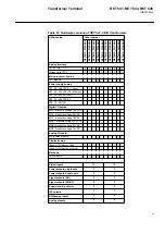
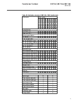
Page 40: ...al inputs and outputs of RET 54_ transformer terminals refer to section Order number above The number of matching transformers and analog inputs and outputs and the auxiliary voltage range vary between the different hardware versions of RET 54_ Moreover RET 541 and RET 543 can be supplied with an RTD analog module For more detailed information about the hardware of RET 54_ refer to the tables 20 2...

Page 41: ... 80 265 VDC AC PS2 18 80 VDC Digital I O boards BIO1 Threshold voltage 155 VDC 1 1 1 1 BIO1 threshold voltage 80 VDC 1 1 1 1 BIO1 threshold voltage 18 VDC 1 1 BIO2 Threshold voltage 155 VDC BIO2 threshold voltage 80 VDC BIO2 threshold voltage 18 VDC Analog I O board RTD analog module 1 1 1 1 1 Display boards Graphic HMI display fixed 1 1 1 1 1 1 Graphic HMI display external 1 1 1 1 Mechanic 1 2 en...

Page 42: ...2 80 265 VDC AC PS2 18 80 VDC Digital I O boards BIO1 threshold voltage 155 VDC 1 1 1 1 BIO1 threshold voltage 80 VDC 1 1 1 1 BIO1 threshold voltage 18 VDC 1 1 BIO2 threshold voltage 155 VDC BIO2 threshold voltage 80 VDC BIO2 threshold voltage 18 VDC Analog I O board RTD analog module 1 1 1 1 1 Display boards Graphic HMI display fixed 1 1 1 1 1 1 Graphic HMI display external 1 1 1 1 Mechanic 1 2 e...

Page 43: ... 80 265 VDC AC PS2 18 80 VDC Digital I O boards BIO1 threshold voltage 155 VDC 1 1 1 1 BIO1 threshold voltage 80 VDC 1 1 1 1 BIO1 threshold voltage 18 VDC 1 1 BIO2 threshold voltage 155 VDC BIO2 threshold voltage 80 VDC BIO2 threshold voltage 18 VDC Analog I O board RTD analog module 1 1 1 1 1 Display boards Graphic HMI display fixed 1 1 1 1 1 1 Graphic HMI display external 1 1 1 1 Mechanic 1 2 en...

Page 44: ...DC AC PS2 18 80 VDC Digital I O boards BIO1 threshold voltage 155 VDC 1 1 1 1 BIO1 threshold voltage 80 VDC 1 1 1 1 BIO1 threshold voltage 18 VDC 1 1 BIO2 threshold voltage 155 VDC 1 1 1 1 BIO2 threshold voltage 80 VDC 1 1 1 1 BIO2 threshold voltage 18 VDC 1 1 Analog I O board RTD analog module 1 1 1 1 1 Display boards Graphic HMI display fixed 1 1 1 1 1 1 Graphic HMI display external 1 1 1 1 Mech...

Page 45: ...DC AC PS2 18 80 VDC Digital I O boards BIO1 threshold voltage 155 VDC 1 1 1 1 BIO1 threshold voltage 80 VDC 1 1 1 1 BIO1 threshold voltage 18 VDC 1 1 BIO2 threshold voltage 155 VDC 1 1 1 1 BIO2 threshold voltage 80 VDC 1 1 1 1 BIO2 threshold voltage 18 VDC 1 1 Analog I O board RTD analog module 1 1 1 1 1 Display boards Graphic HMI display fixed 1 1 1 1 1 1 Graphic HMI display external 1 1 1 1 Mech...

Page 46: ...DC AC PS2 18 80 VDC Digital I O boards BIO1 threshold voltage 155 VDC 1 1 1 1 BIO1 threshold voltage 80 VDC 1 1 1 1 BIO1 threshold voltage 18 VDC 1 1 BIO2 threshold voltage 155 VDC 1 1 1 1 BIO2 threshold voltage 80 VDC 1 1 1 1 BIO2 threshold voltage 18 VDC 1 1 Analog I O board RTD analog module 1 1 1 1 1 Display boards Graphic HMI display fixed 1 1 1 1 1 1 Graphic HMI display external 1 1 1 1 Mech...

Page 47: ...l I O boards BIO1 threshold voltage 155 VDC 2 2 BIO1 threshold voltage 80 VDC 2 2 BIO1 threshold voltage 18 VDC 2 BIO2 threshold voltage 155 VDC 1 1 BIO2 threshold voltage 80 VDC 1 1 BIO2 threshold voltage 18 VDC 1 Analog I O board RTD analog module Display boards Graphic HMI display fixed 1 1 1 Graphic HMI display external 1 1 Mechanic 1 2 enclosure 1 1 1 1 1 Digital inputs 34 Power outputs singl...

Page 48: ...l I O boards BIO1 threshold voltage 155 VDC 2 2 BIO1 threshold voltage 80 VDC 2 2 BIO1 threshold voltage 18 VDC 2 BIO2 threshold voltage 155 VDC 1 1 BIO2 threshold voltage 80 VDC 1 1 BIO2 threshold voltage 18 VDC 1 Analog I O board RTD analog module Display boards Graphic HMI display fixed 1 1 1 Graphic HMI display external 1 1 Mechanic 1 2 enclosure 1 1 1 1 1 Digital inputs 34 Power outputs singl...

Page 49: ...l I O boards BIO1 threshold voltage 155 VDC 2 2 BIO1 threshold voltage 80 VDC 2 2 BIO1 threshold voltage 18 VDC 2 BIO2 threshold voltage 155 VDC 1 1 BIO2 threshold voltage 80 VDC 1 1 BIO2 threshold voltage 18 VDC 1 Analog I O board RTD analog module Display boards Graphic HMI display fixed 1 1 1 Graphic HMI display external 1 1 Mechanic 1 2 enclosure 1 1 1 1 1 Digital inputs 34 Power outputs singl...

Page 50: ...onality level can be activated within the scope of the I O connections and considering the total CPU load of the func tions Parts and assembly descriptions To achieve the best possible operation accu racy all parts of a RET 54_ product have been calibrated together Thus each product forms a whole for which no separate spare parts can be supplied In the event of mal function please consult your tra...

Page 51: ...anger is used to increase the sensitivity of the differential function of the transformer In this example the voltage controller is not included in the RET 543 transformer terminal Yd transformer 3DI 87TG 3I U TCS R 51 3I 50 51N 50N I 0 62BF CBFP 3 49T 51 3I 50 HV LV HV HV 62BF CBFP LV P Q O T 2 I 46 w T 3I U Io CBCM HV 62BF REF 54_ CBFP U 0 59N 51 50 3I 3U 3U 27 59 3U TCS R 3I RET 54_ P Q 3I 3I 2...

Page 52: ...n be applied also for parallel connected transformers Dyn trafo_impEarthedLVn MF MF RET 3I REF 4I RET 3I REF 3I RET 1I REF 1I RET RTD RET 1U REF 3U 3DI 87T RET 54_ 3I U TCS R 51 3I 50 51N 50N I 0 68 3I 3 49T 51 3I 50 HV LV HV 62BF CBFP HV 2 I 46 HV 0 DI 87TN LV 51N 50N I 0 LV I0 3I I0 TO Tw o o 90 CBFP LV 62BF U U 3U 3I 51N 0 I REF 54_ CBFP 62BF 50N 3I 50 51 3U 3U 27 59 R TCS I0 P Q 50N 62BF REF 6...

Page 53: ... 0 3I ΔI 0 HV ΔI 0 LV 87TN 49T 87TN 3ΔI 87T 0 I I HV 0 LV 3I 51N 51N 50N I 50 51 HV 3I 50 51 U I0 HV 000 000 TCS R 3I 3U 62BF CBFP REF 54_ I 0 50N 51N f 3U 81O 27 3I 67 3U 59 I0 3I harm pf P Q f 3I 3U harm E REA 101 df dt 81O R 000 000 R TCS 3U 3I 51N 0 I REF 54_ CBFP 62BF 50N 2f 3I 3I 68 50 51 3U 3U 27 59 I0 M M M M M M M M YNd transformer with earthing transformer on LV side M M MF MF P Θ Θ RET ...

Page 54: ...applied also for parallel con nected transformers RET 3I REF 3I REF REA 3I RET 3I RET 1I REF 1I REF 1I RET 1I REF 3U REF 3U REF 3U RET 1U RET RTD P Θ Θ df dt I CBFP 62BF 51N 50N 0 R TCS CBCM MCS E 27 59 3U 3U 3U 0 I 3I REF 54_ 67 3I f 81O pf f 3I REA 101 81O R 000 3 U R TCS U 3ΔI 87T RET 54_ 3I U 51 3I 50 51N 50N I 0 62BF CBFP 49T 51 3I 50 HV LV HV HV 62BF CBFP LV 87TN LV 51N 50N I 0 LV I0 ΔI 0 87...

Page 55: ...01 3I RET 3I Basic REF 3U RET 1U Multi RET 1I Basic RET 3I Multi RET 4I Basic REX 1U REX 3U RET 2U Multi REF 1I 3DI 87TG 3I TCS R 000 51 3I 50 51N 50N I 0 62BF CBFP 3 49T 51 3I 50 HV LV HV LV 62BF CBFP HV 0 DI 87TN LV 51N 50N I 0 LV I0 I0 3I 3I 3U 50 62BF CBFP I 0 50N 51N U 0 3U 59N 27 3I 51 3U 59 TCS I0 R RET 54_ Basic REF 54_ 3I 68 3I 2f REX 521 H06 U 59N 3U 3U 27 59 TCS MCS CBCM R 3U U0 000 p Q...

Page 56: ...3I RET_ 1I REM_ 3I REM_ 3U REM_ 3I RET_ 3I REX521 1U REX521 3U REM RTD REM_ 1U T O T o o w 0 U 0 I 3I 3I I TCS R RET 54_ 87TN 46 I 2 HV LV DI 0 3 49T 0 I 51N HV CBFP LV 50N 62BF I HV 0 3I LV 51N 50N 50 51 3DI 87TG HV 3I 50 51 3U 59 U 59N 81U f f 0 U MCS TCS R 000 REX 521 H06 CBCM 3U 27 3U 0 87G 3DI 3I 51 50 50N I I U 51V 3U 59 59N U 38 49 60 F 49G 46 32 I 3 P 40 X f 3I U0 Q P TCS U R 000 MCS pf RE...

Page 57: ...nn trafo2 3 G MF REK 510 RET_ 3I RET_ 1U RET_ 1U RET_ 1I REM_ 3I A REM_ 3I B REM_ 2U A 3U B REM_ 1U A REM_ 3I A REM_ 1I A RET_ 3I REM I0R B Q P Q 3U 59 CBFP Z P REM 54_ B 3 59N 27 U0 3U F 64R 50 51 IOR 3I 62BF 60 f 49G 32 0 U Q 3I MCS TCS pf 3U P R 21G 000 U f 24 E 87G 3DI 64S I 46 I f 3I Q P TCS U R 000 MCS pf REM 54_ A CBFP 62BF f f 81O 81U X 40 P 32 2 E os RET 54_ 87TN 46 I 2 HV LV DI 0 3 49T 0...

Page 58: ...negative phase sequence NPS protection low set and high set stages available NPS3_ underfrequency protection and frequency rate of change function incl in Freq1St_ three phase differential protection for transformers stabilized and instantaneous stages Diff3 restricted earth fault REF protection low or high impedance type Diff3 circuit breaker failure protection included in all current based short...

Page 59: ...nual voltage regulation COLTC active power measurement indication and supervision reactive power measurement indication and supervision 3 phase current measurement indication and supervision 3 phase voltage or phase to phase voltage measurement indication and supervision frequency measurement indication and supervision power factor measurement indication and supervision residual current measuremen...

Page 60: ...ement PQCU3H annunciating event generating and value recording functions disturbance recorder MEDREC16 digital value indication HMI MIMIC display local and remote control interface bay oriented interlocking logic voltage waveform distortion measurement PQVU3H oil temperature measurement indication and supervision transformer winding temperature measurement indication and supervision tap changer te...

Page 61: ...Low 67 3I Three phase directional o c high set stage DOC6High 67 3I Three phase directional o c instantaneous stage DOC6Inst Underimpedance 21 Z Three phase underimpedance low set stage UI6Low 21 Z Three phase underimpedance high set stage UI6High Earth fault 51N Io SEF Non directional earth fault low set stage or SEF sensitive earth fault protection NEF1Low 50N 51N Io Non directional earth fault ...

Page 62: ...tion stage 1 PSV3St1 27 47 59 U1 U2 U1 Phase sequence voltage protection stage 2 PSV3St2 Overfrequency underfrequency 81U 81O f f df dt Underfrequency or overfrequency stage 1 incl rate of change Freq1St1 81U 81O f f df dt Underfrequency or overfrequency stage 2 incl rate of change Freq1St2 81U 81O f f df dt Underfrequency or overfrequency stage 3 incl rate of change Freq1St3 81U 81O f f df dt Und...

Page 63: ...oltage measurement stage A MEVO1A Uo Residual voltage measurement stage B MEVO1B Energy Power E P Q pf Three phase power and energy measurement MEPE7 Frequency f System frequency measurement MEFR1 Recording Transient disturbance recorder MEDREC16 Transformer Terminal RET 541 RET 543 RET 545 1MRS755543 63 Table 32 Control functions Types of control Symbol Control function Function block code Circui...

Page 64: ...c wear 1 CMBWEAR1 CBCM CB electric wear 2 CMBWEAR2 CBCM Operate time counter 1 for used operate time motors CMTIME1 CBCM Operate time counter 2 for used operate time motors CMTIME2 CBCM Gas pressure monitoring CMGAS1 CBCM Three pole gas pressure monitoring CMGAS3 CBCM Spring charging control 1 CMSPRC1 CBCM Breaker travel time 1 CMTRAV1 CBCM Scheduled maintenance CMSCHED Trip circuit TCS Trip Circu...

Page 65: ...MUM Protection Control Terminals REF 54_ REM 54_ RET 54_ and REC 523 Configuration Guideline 1MRS750745 MUM Bus Connection Module RER 133 Technical Description 1MRS755163 Echelon LON and LonTalk are registered trademarks of Echelon Corporation All other product names or brands are trademarks registered trademarks or service marks of their respective owners Document changes Version Date Changes C 1...

Page 66: ......

Page 67: ......

Page 68: ...ABB Oy Distribution Automation P O Box 699 FI 65101 Vaasa FINLAND Tel 358 10 22 11 Fax 358 10 224 1094 www abb com substationautomation ...

Reviews: