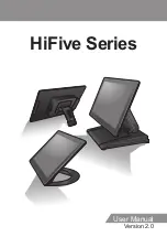
Datavan HiFive Series User Manual Download Page 1

HiFive Series

Version 2.0

User Manual

Summary of Contents for HiFive Series

Page 1: ...HiFive Series Version 2 0 User Manual...

Page 2: ...ructions in this manual will void this product s warranty Power Supply Safety Notes To avoid electric shocks disconnect the power cord from the electrical outlet before relocating the system Make sure...

Page 3: ...the screen or the casing of the terminal Chemical cleaners have been reported to cause damage on the screen of the terminal Warning and Attention The technical descriptions and specifications of the e...

Page 4: ...r there is no guarantee that interference will not occur in a particular installation If this equipment does cause harmful interference to radio or television reception which can be determined by swit...

Page 5: ...oduct or on its box indicates that this product must not be disposed of or dumped with your other household waste You are liable to dispose of all your electronic or electrical waste equipment by relo...

Page 6: ...Setting and Connector Definition 31 U 615 31 Voltage Output Definition 33 U 615 33 Setting the LCD Brightness 34 U 615 LVDS Panel 34 U 615 eDP Panel 35 Chapter 3 Hardware Installation 36 Adjusting th...

Page 7: ...7 Chapter 4 Frequently Asked Questions FAQ 44 Question 1 How do I clear CMOS 44...

Page 8: ...omer experience Package Contents Before setting up your Touch Terminal check that the package contains the following items If any of the items is missing or damaged contact your vendor immediately Tou...

Page 9: ...in this section illustrate the components including input and output ports located at the front and rear of your Touch Terminal Front View NANO Stand Type Wall Mounting Type H 610 H 614 H 615 LITE Sta...

Page 10: ...10 INTRODUCTION Rear View NANO Stand Type H 610 H 614 LITE Stand Type H 610 H 614 FLEX Stand Type H 610 H 614 H 615...

Page 11: ...FF USB 2 0 USB 2 0 USB 3 0 LINE OUT Bottom Item Description DK port Cash Drawer output COM 1 2 ports COM connectors USB2 0 ports USB2 0 connectors Line Out port Audio line output connector DC IN jack...

Page 12: ...12 INTRODUCTION Physical Dimensions VESA Mount H 610...

Page 13: ...INTRODUCTION 13 H 614 H 615...

Page 14: ...14 INTRODUCTION Standard Display NANO Stand Type H 610 NANO Stand Type H 614...

Page 15: ...INTRODUCTION 15 LITE Stand Type H 610 LITE Stand Type H 614...

Page 16: ...16 INTRODUCTION FLEX Stand Type H 610...

Page 17: ...INTRODUCTION 17 FLEX Stand Type H 614...

Page 18: ...18 INTRODUCTION FLEX Stand Type H 615...

Page 19: ...INTRODUCTION 19 VFD Customer Display LITE Stand Type H 610...

Page 20: ...20 INTRODUCTION LITE Stand Type H 614 FLEX Stand Type H 610...

Page 21: ...INTRODUCTION 21 FLEX Stand Type H 614...

Page 22: ...22 INTRODUCTION FLEX Stand Type H 615...

Page 23: ...INTRODUCTION 23 Secondary LCD Display FLEX Stand Type H 610...

Page 24: ...24 INTRODUCTION FLEX Stand Type H 614...

Page 25: ...INTRODUCTION 25 FLEX Stand Type H 615...

Page 26: ...x 8GB Graphic Memory Shared memory up to 1696 MB Intel DVMT Storage 1 x M 2 Socket 2280 Size S ATA II 64GB default 256GB I O Ports M B U5A J1900 USB2 0 4 USB3 0 1 RJ50 COM 2 DC 5V 12V select by Jumper...

Page 27: ...re subject to change without notice Peripherals Specifications Secondary LCD Display Model no KEKLC 3318A LCD Panel 10 1 LED backlight Touch 10 1 PCT 4 3 USB optional Resolution 1024 x 768 Aspect Rati...

Page 28: ...ter Type 95 Alphanumeric 32 International characters Dot Size 0 55 W X 0 75 H mm Viewing Angle Max 90 Horizontal Rotation Max 355 Interface RS232 NOTE Pre setting the output voltage of COM port is nee...

Page 29: ...orized person Before installation or disassembling of the terminal ensure that the power is turned off Otherwise electric shock may occur and may void the warranty For systems preloaded with WEPOS POS...

Page 30: ...PREPARING FOR THE INSTALLATION System Default Settings The following is the information on default settings for Touch Terminal serial ports U 615 COM1 COM2 COM3 COM4 3F8 2F8 3E8 2E8 IRQ4 IRQ3 IRQ5 IRQ...

Page 31: ...umper Description LED2 Power status light LOUT1 Audio line output connector DC1 12V DC power input LAN1 LAN connector RJ45 USB2 USB2 0 x2 connector USB1 USB3 0 x1 connector CASHDRAW1 Cash Drawer outpu...

Page 32: ...er connector COM3 COM3 connector for RS 232 POS input device JST2 0 1x9 JUSB1 USB port for POS input device JUSB2 USB port for USB Touch EDP1 eDP LED Panel LVDS1 LVDS LED Panel SATA1 M 2 M key SATA ty...

Page 33: ...ocation Power Support COM 1 for extension interface 9th PIN of DB 9 Main Board DC5V DC12V Select by jumper COM 2 for extension interface 9th PIN of DB 9 Main Board DC5V DC12V Select by jumper COM 3 fo...

Page 34: ...LCD Brightness U 615 LVDS Panel 1 When the system boots up press F2 to enter the BIOS Setup Utility Select the Advanced tab then select Video Configuration 2 Select LVDS Brightness Control Level and...

Page 35: ...35 U 615 eDP Panel 1 When the system boots up press F2 to enter the BIOS Setup Utility Select the Advanced tab then select Video Configuration 2 Select eDP Brightness Control Level and set the desire...

Page 36: ...damaged 1 Place the Touch Terminal on a stable surface and carefully lift the LCD panel 2 Support the stand firmly with one hand while pushing the back of the LCD panel backwards with the other hand 3...

Page 37: ...Because the stand joints are tight you might need to exert someforce to maneuver the Terminal Make sure always rotate around the head to the position a before adjusting the upper hinge Adjusting the S...

Page 38: ...over b 3 Route the power adapter and the network cable through the cable compartment c 4 Connect the network cable to the LAN port Then connect the power adapter to the DC IN jack d 5 Use the cable cl...

Page 39: ...tand to the Touch Terminal a 2 Remove the four screws securing the stand to the Touch Terminal b 3 Remove the stand c 4 Remove the VESA compartment cover d 5 Remove the I O port cover e 6 Detach the c...

Page 40: ...rt cover c 5 Align and place the customer display on the rear of the Touch Terminal d 6 Place the stand on the top of the customer display bracket b 7 Route the customer display cable as shown in the...

Page 41: ...Deattach the cable compartment cover from the secondary LCD display e 6 Route the secondary LCD display USB Y cable through the cable guides on the stand as illustrated f 7 Install the stand c and se...

Page 42: ...e making any connection or disconnection 1 Remove the MSR module compartment cover a 2 Firmly connect the MSR connector into the slot inside the compartment b 3 Remove the two screws from the compartm...

Page 43: ...l with the four screws b 3 Drill four small holes on the mounting location and insert the plastic washers into the holes c 4 Align by the screw holes and then install the wall bracket on the wall d 5...

Page 44: ...ing 1 Turn off the power and pull out the power cord 2 Remove the battery from the BAT1 connector about 15 seconds and then restore 3 Switch on the power again First trigger is pre boot for CMOS backf...

Reviews: