background image

Clock synchronization

Day of week used

RES1, GEN (time tag substituted/ not substituted) used

SU-bit (summertime) used

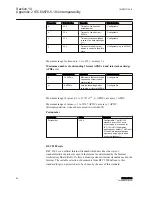
Command transmission

(Object-specific parameter, mark with an “X“ if the function is only used in the
standard direction, “R“ if only used in the reverse direction, and “B“ if used in both
directions.)

Direct command transmission

Direct set point command transmission

Select and execute command

Select and execute set point command

C_SE ACTTERM used

No additional definition

Short-pulse duration (duration determined by a system parameter in the outstation)

Long-pulse duration (duration determined by a system parameter in the outstation)

Persistent output

Supervision of maximum delay in command direction of commands and set point commands

Maximum allowable delay of commands and set point commands

Transmission of integrated totals

(Station- or object-specific parameter, mark with an “X“ if the function is only
used in the standard direction, “R“ if only used in the reverse direction, and “B“ if
used in both directions.)

Mode A: Local freeze with spontaneous transmission

Mode B: Local freeze with counter interrogation

Mode C: Freeze and transmit by counter-interrogation

commands
Mode D: Freeze by counter-interrogation command, frozen

values reported


Table continues on next page

1MRS757105 B

Section 10

Appendix 2 IEC 60870-5-104 interoperability

RER601/603

89

Technical Manual

Summary of Contents for RER601

Page 1: ...Wireless Gateway RER601 603 Technical Manual ...

Page 2: ......

Page 3: ...Document ID 1MRS757105 Issued 2014 08 18 Revision B Product version 1 2 Copyright 2014 ABB All rights reserved ...

Page 4: ...rdance with the terms of such license Trademarks ABB and Relion are registered trademarks of the ABB Group All other brand or product names mentioned in this document may be trademarks or registered trademarks of their respective holders ABB is a registered trademark of the ABB Group All other brand or product names mentioned in this document may be trademarks or registered trademarks of their res...

Page 5: ...cted and communicate data and information via a network interface which should be connected to a secure network It is the sole responsibility of the person or entity responsible for network administration to ensure a secure connection to the network and to take the necessary measures such as but not limited to installation of firewalls application of authentication measures encryption of data inst...

Page 6: ...Conformity This product complies with the following Electro Magnetic Combatibility EMC standards ETSI EN 301489 1 V1 8 1 2008 04 IEC 61000 6 1 Second edition 2005 01 and IEC 61000 6 3 2006 07 ...

Page 7: ...h 9 DIP switches 9 Back panel 9 Console serial port 1 10 Ethernet 11 Power supply connector 11 Side panel 12 DIN rail mounting 13 Product label 13 Firmware version 13 Section 3 Physical connections 15 Serial ports 15 Serial port 2 15 GPRS 16 RER603 I O extension 17 Section 4 Cyber security 19 Enhancing operator and subscription security 19 Configuring firewall and services 19 Section 5 RER601 603 ...

Page 8: ...ettings 46 Serial settings 46 Network settings 47 IEC 104 settings 49 IEC 101 settings 52 ASDU converter 56 Packet collector 57 Other settings 58 IEC 104 I O application settings 59 Support for remote monitoring 59 Section 6 Troubleshooting 61 Setting up the routing mode 61 Restoring Ethernet connection 61 Using the M2M Gateway with one public IP 61 Receiving characters from the console 61 Setting...

Page 9: ...ling the SIM card 72 Setting the IP address via a Web browser 72 Configuring the GPRS settings 75 Section 10 Appendix 2 IEC 60870 5 104 interoperability 77 Interoperability 77 System or device 78 Network configuration 78 Physical layer 78 Link layer 79 Application layer 80 Basic application functions 87 Section 11 Glossary 95 Table of contents RER601 603 3 Technical Manual ...

Page 10: ...4 ...

Page 11: ...ers and installation and commissioning personnel who use technical data during engineering installation and commissioning and in normal service 1 3 Product documentation 1 3 1 Document revision history Document revision date Product series version History A 2011 09 02 1 0 First release B 2014 08 18 1 2 Content updated Download the latest documents from the ABB Website http www abb com substationau...

Page 12: ...ertain function Although warning hazards are related to personal injury it is necessary to understand that under certain operational conditions operation of damaged equipment may result in degraded process performance leading to personal injury or death Therefore comply fully with all warning and caution notices 1 4 2 Manual conventions Conventions used in manuals A particular convention may not b...

Page 13: ... Static IP addresses Firewall and VPN IEC 104 TCP IP Wireless Gateway RER601 603 SPA IEC 101 ABB IED GPRS Secure end to end VPN tunneling in public network GUID EB58A974 9E55 4A09 B29A 912E5411F1BD V1 EN Figure 1 Typical connection The device contains three panels for interface connections and status indication The front panel includes all the connectors and switches for the device s operation opt...

Page 14: ...sole serial port RS1 3 Power switch 4 Console switch 5 Application serial port RS2 6 DIP switches 7 I O extension only available for RER603 8 Ethernet connector The device has rails for wall or rack mounting The front panel contains slots for nuts or other optional mounting accessories to gain access to the rails 2 2 1 Power switch Use the power switch to switch the device s power on or off Sectio...

Page 15: ... 485 mode is selected with DIP switch 1 Table 1 DIP switches Number Function State Description 1 RS 232 RS 485 0 RS 232 1 RS 485 Selects the RS port operation 2 HALF FULL 0 full 1 half Selects between half duplex 2 wire and full duplex 4 wire 3 BIAS 0 OFF 1 ON Turns RS 485 biasing on or off 4 TERMINATION 0 OFF 1 ON Turns RS 485 termination on or off 2 3 Back panel The IEC 60870 5 104 gateway has a...

Page 16: ... description Pin number Name Direction Description 1 DCD IN Data Carrier Detect 2 RXD IN Received data 3 TXD OUT Transmitted data 4 DTR OUT Data Terminal Ready handshake output 5 GND Signal ground 6 DSR IN Data Set Ready handshake input 7 RTS OUT Ready To Send handshake output 8 CTS IN Clear To Send handshake input 9 RI IN Ring Indicator Section 2 1MRS757105 B RER601 603 overview 10 RER601 603 Tec...

Page 17: ...2 V1 EN Figure 4 RJ 45 Ethernet connector Table 3 RJ 45 Ethernet connector PIN description Pin number Name Direction Description 1 Rx IN Data Receive Positive 2 Rx IN Data Receive Negative 3 Tx OUT Data Transmit Positive 4 NC 5 NC 6 Tx OUT Data Transmit Negative 7 NC 8 NC 2 6 Power supply connector The device has a 10 26 V DC power supply connector The unit is protected against reversed polarity G...

Page 18: ...onnection is up Blinking VPN onnection is starting Off VPN connection is disabled 3 Power Error On Operating power is turned on Off Operating power is turned off 4 Function On Device is starting Blinking Device is operating normally Off Device is not operational 5 Eth 1 On Ethernet link is up Blinking Ethernet link is transferring data Off Ethernet link is down 6 Eth 2 LED reserved for future func...

Page 19: ... the device It contains the basic information about the unit such as product name serial number and Ethernet MAC address GUID 83091CC0 F7B9 45F0 9B27 204F6B5ACE9F V1 EN Figure 7 Product label 2 10 Firmware version The device firmware version can be checked from the REC601 603 configurator start page System Information or by executing the firmware command via the console This manual describes the R...

Page 20: ...GUID 73E7240B 920B 48AE 935C AC393DEC9C84 V1 EN Figure 8 Firmware version Section 2 1MRS757105 B RER601 603 overview 14 RER601 603 Technical Manual ...

Page 21: ...2 can be configured either as a half RS 232 or an RS 422 485 DTE Master The pin description is the same as in RS1 when the port is in the RS 232 mode Do not connect the RS 422 or RS 485 devices to a port which has been configured to operate as an RS 232 port Table 5 RS 485 port PIN description Pin number RS 485 full duplex 4 wire RS 485 half duplex 2 wire 1 NC NC 2 RXD in NC 3 TXD out TXD RXD out ...

Page 22: ...vice s IEC 60870 5 104 gateway is tested with antennas from Hirschmann Rheinmetall Elektronik GmbH Examples of tested external antennas include the sticker type and magnetic mount antennas GUID 12B0663A 5DB4 4A30 BC92 D3A7937C2A03 V1 EN Figure 10 Sticker type patch antenna MCA 18 90 STRIPE GUID 0EBA8EC3 4484 4EF5 B82E 205510850BA7 V1 EN Figure 11 Magnetic mount antenna MCA 18 90 MH Both antennas h...

Page 23: ...and alarm acknowledgement GUID 9E610926 032D 486F AB59 CFBF3D85396C V1 EN Figure 12 RER603 I O extension Table 6 RER603 I O connector pins PIN Symbol Description 1 V Vcc out 50 mA 2 DI_1 Digital input 0 60V 3 DI_2 Digital input 0 60V 4 DI_3 Digital input 0 60V 5 DI_4 Digital input 0 60V 6 DI_5 Digital input 0 60V 7 DI_6 Digital input 0 60V 8 DI_7 Digital input 0 60V 9 DI_8 Digital input 0 60V 10 D...

Page 24: ...l Description 12 DO_1B Digital output pole 2 13 DO_2A Digital output pole 2 0 60V 50 mA 14 DO_2B Digital output pole 2 15 GND GND output Section 3 1MRS757105 B Physical connections 18 RER601 603 Technical Manual ...

Page 25: ...g operator and subscription security Network subscription and SIM card must be stored safely and configured to prevent misuse of services Disable unused services from SIM cards Voice calls SMS Paid services Roaming Use pin code in SIM cards Prefer a private APN service from the operator Prefer M2M subscription SIM cards from the operator Use private IP addressing from the operator for GPRS communi...

Page 26: ...w only the needed ports Set unique passwords for each device Keep passwords stored in a safe place for example Encrypted password management tool Check that all unused services are disabled If possible allow IP connections only via VPN Disable all unused services for example Dial in SMSconfig serial and SNMP Back up the configuration Section 4 1MRS757105 B Cyber security 20 RER601 603 Technical Ma...

Page 27: ...ween the different subsets of the available settings Selecting an item from the main menu displays the available items related to this subset in the navigation bar The first of these is displayed in the content area by default The navigation bar on the left contains the parameter groups in the subset Selecting an item from this menu displays the content related to the selected group in the content...

Page 28: ...ecting the device to a public network Change the password from the System Password menu GUID 02E3F702 FFDB 4592 86D3 8D15B407E906 V1 EN Figure 14 System login 5 3 System menu The System menu can be used to view information about the system or the current executing environment and to set the date and time Updated time information is not saved permanently until the Commit button is pressed Section 5...

Page 29: ... before connecting the device to a public network The default password for the root account is empty 1 Click Password When changing the password for the first time type the new password in all three fields Old password Password and Retype password When changing an old password type the old password in the Old password field type the new password in the Password field and retype the new password in...

Page 30: ... the currently active interfaces and routing information GUID 79E31C82 384A 43C2 B20A 03B30CFC7994 V1 EN Figure 16 Network interface summary 5 4 1 Ethernet The device s Ethernet interface is configured via the Ethernet command in the Network menu Clicking this command displays the Ethernet settings in the content area Section 5 1MRS757105 B RER601 603 Configurator 24 RER601 603 Technical Manual ...

Page 31: ...by the eth0 interface Network mask determines the network mask used by the eth0 interface Use Ethernet as default route should be set to Yes only if Ethernet is used as the default gateway or router Usually this parameter is set to No because either GPRS or VPN is used as the default route This parameter overrides the next parameter Default Route IP Address so that parameter has no effect if Use E...

Page 32: ...r settings for the GPRS network connection GUID 65FCF788 2220 4425 9226 24CF29513B32 V1 EN Figure 18 GPRS settings GPRS enabled When set to Yes the GPRS interface is automatically connected to the GPRS network Access Point Name GPRS determines the GPRS Access Point Name APN for the connection PIN code determines the SIM card PIN code Operator Code empty auto is a manually selected operator code Le...

Page 33: ...default route The Ethernet default gateway has to be disabled by setting the parameter Use Ethernet as default route to No in Network Ethernet 5 4 3 Dial in The device s PPP dial in interface is configured via the Dial in command in the Network menu Clicking this command displays the Dial in settings in the content area Dial in enabled If enabled PPP connections can be made to the device GSM data ...

Page 34: ...o Yes the device automatically establishes a SSH VPN connection to the primary gateway Primary interface determines the interface used to reach the gateway server Primary server IP determines the IP address of the gateway SSH VPN server Section 5 1MRS757105 B RER601 603 Configurator 28 RER601 603 Technical Manual ...

Page 35: ...nnection Backup server optional Use backup SSH VPN When set to Yes the device tries to establish a VPN connection to back up the gateway if the primary gateway cannot be reached Primary failure limit determines the number of times the primary must not be reached before changing to the secondary The other parameters are same as in the primary server The duration of the connection can be set for exa...

Page 36: ...dle timeout sec determines the idle time out for the SSH VPN interface If the time out is reached the VPN connection is restarted 5 4 5 L2TP VPN The device has an L2TP client that can be used with an L2TP server Section 5 1MRS757105 B RER601 603 Configurator 30 RER601 603 Technical Manual ...

Page 37: ...primary server cannot be reached the L2TP VPN connection is established with a backup server Primary server Use L2TP VPN When set to Yes the device establishes an L2TP VPN connection with the primary gateway 1MRS757105 B Section 5 RER601 603 Configurator RER601 603 31 Technical Manual ...

Page 38: ...ed if routing is needed with the L2TP interface The parameters are the same as for SSH VPN 5 4 6 GRE The GRE tunnel command in the Network menu is used to configure theGRE settings GRE tunnel enabled When set to Yes the device establishes the GRE connection automatically Interface determines the interface used for the GRE server GRE server IP determines the IP address of the GRE server Gw to GRE s...

Page 39: ... When VPN is used the remote VPN peer IP address or other IP address reached only via VPN must be used for checking the connection Interval sec determines how often the connection is checked by sending ICMP echo packets The interval should be smaller than the GPRS idle time out typically maximum 2 3 of GPRS idle time out for uninterrupted communication Reply timeout secs determines the waiting tim...

Page 40: ... to the local IP address Source IP determines the D NAT connections coming from the IP address If defined with wildcard 0 0 all IP addresses are handled in the same way Protocol determines the protocol that is forwarded If the value Any is selected other parameters are ignored Dest port determines the GPRS interface that is forwarded to the local Ethernet Redirect to IP determines the IP address u...

Page 41: ...mple the company s own DNS server such as ISC BIND TSIG key name TSIG keys can be used for better security in DNS updates 5 4 8 4 DynDNS client These settings can be used with the DynDNS service available at http www dyndns org The public IP address is required for GPRS and the user account from the DynDNS service operator 1MRS757105 B Section 5 RER601 603 Configurator RER601 603 35 Technical Manu...

Page 42: ...4 8 5 NTP client The NTP client settings can be used to update the real time clock of the device using the NTP protocol NTP server When enabled the device updates the system clock from the NTP server Query interval determines the time interval for an NTP query Minimum time difference seconds determines the minimum time difference when the clock is updated Maximum time difference determines the max...

Page 43: ...m password is required for set commands Allow execute commands determines if execute commands are allowed to be run on the device Other Reply error to unknown commands If set to No incorrect commands are silently disregarded If set to Yes the device sends an error message via SMS Reply error to unauthorized commands If set to No unauthorized commands are silently disregarded If set to Yes the devi...

Page 44: ...rom top to bottom If strict rules are wanted the last rule should be DROP The parameter From IP can be used to limit access based on the IP address For example 192 168 100 0 24 would limit access to packets coming from the 192 168 100 0 network only Section 5 1MRS757105 B RER601 603 Configurator 38 RER601 603 Technical Manual ...

Page 45: ...nnection to the GPRS interface ICMP Web TCP port 80 and Telnet TCP port 22 from any IP access 5 6 Service menu The Service menu contains the settings for the WWW SSH Telnet and DHCP servers 5 6 1 WWW These settings are used to enable or disable the WWW server 1MRS757105 B Section 5 RER601 603 Configurator RER601 603 39 Technical Manual ...

Page 46: ...edited manually SSH Server enables or disables the SSH server 5 6 3 Telnet A Telnet server can be used to make terminal connections to the device shell A more secure way of performing remote management is based on the SSH Telnet server enables or disables the Telnet server 5 6 4 DHCP The DHCP server listens to broadcast DHCP queries and assigns an IP address for the host from the configured pool I...

Page 47: ...d to the device s Ethernet interface to use the device as a DNS server The device forwards DNS queries to the correct DSN server and there is no need to change the local computer s DNS settings This can be used with the GPRS settings Network GPRS parameter DNS servers From GPRS network DNS Proxy Forwarder enables the use of the device as a DNS server for local computers SNMP Agent enables the use ...

Page 48: ... community string Server port standard 161 determines the SNMP Agent listening port UDP Bind to interface determines that the interface is used as a source address 5 7 Application menu The Application menu contains the serial device server application With this application serial devices can be connected to the gateway and used over the TCP IP network Section 5 1MRS757105 B RER601 603 Configurator...

Page 49: ...peration mode the gateway sends the received serial data via TCP IP to the host remote IP address or host or to the remote host remote port The IEC 60870 5 104 serial device can be connected to the RS1 or RS2 port The RS2 serial port can be used either as an RS 232 or an RS 485 type port IEC 60870 5 104 To enable the serial gateway on the console RS1 port the console switch has to be set to 0 1MRS...

Page 50: ... Console The console settings can be used for running commands over the WHMI Example commands ping c 10 172 30 30 1 firmware System Log and Recent events The device s system log can be viewed as a system log and a recent events log When support for the device is needed for example in a fault situation the log files can be copy pasted from the system log Modem info Displays information about the GP...

Page 51: ... By using the device s IEC 60870 5 104 gateway the IEC 60870 5 101 slaves for example RTUs can be connected to an IEC 60870 5 104 master for example SCADA The device requests events from the IEC 60870 5 101 slave locally and sends them to the IEC 60870 5 104 master This eliminates the need to continuously poll the data remotely and also reduces the communication costs on a pay per use GPRS network...

Page 52: ... or RS2 single device per port When the serial port RS1 is used the console switch below the RS1 should be in the Data position The settings for the IEC 104 gateway applications are available on WEB user interface applications IEC 104 RS1 and IEC 104 RS2 GUID ADB6008D 9F4F 44EB A13F 799CC98EFBCD V1 EN Figure 31 Serial settings Speed bps defines the IEC 60870 5 101 serial communication speed bps Ta...

Page 53: ...l communication Table 11 Number of stop bits used in the IEC 60870 5 101 serial communication Description Value Type Serial data stop bits Units Bits Value range 1 2 Note Use HW flow control defines if the HW flow control mechanism is used Table 12 HW flow control mechanism RTS CTS in the IEC 60870 5 101 serial communication Description Value Type Boolean Units N A Value range Yes No Note The HW h...

Page 54: ...r UDP port to listen for incoming IEC 60870 5 104 connections Description Value Type Network port Units Port number Value range 0 65000 Note The IEC 60870 5 104 standard specifies TCP port 2404 Network idle timeout defines the idle time out of the network connection in seconds If there is no network data received during the specified interval the device closes the connection This parameter is requ...

Page 55: ...e IEC 104 settings define the properties of the IEC 60870 5 104 link layer and application layer parameters as described in the IEC 60870 5 104 standard The IEC 60870 5 104 communication is carried out between the device and the IEC 60870 5 104 master over the TCP IP network GUID C17C8A3A 9A94 47FC A82F DCB64D418132 V1 EN Figure 33 IEC 104 Settings TX window size k defines the maximum number of I ...

Page 56: ...tandard suggests w 8 I frames TX timeout t1 defines the time out in seconds the device waits for an acknowledgement from the IEC 60870 5 104 master after sending the last I format APDU or a control frame such as a link test If no acknowledgement is received during the defined time the device closes the network connection and the IEC 60870 5 101 link Table 19 IEC 60870 5 104 I frames TX time out t1...

Page 57: ...ntially longer for pay per use GPRS connections Suspended timeout defines the time in seconds how long a connected IEC 60870 5 104 link can be in the suspended state STOPD before the device closes the connection Table 22 IEC 60870 5 104 suspended time out Description Value Type Timeout Units Seconds Value range 1 65000 Note Using this parameter makes it easier to detect partially closed network co...

Page 58: ...0 5 104 standard defines the value 2 Info object address length defines the length of the IEC 60870 5 104 Information object address ASDU header field in bytes Table 26 IEC 60870 5 104 ASDU information object address length Description Value Type Field length Units Bytes Value range 1 3 Note The IEC 60870 5 104 standard defines the value 3 5 9 5 IEC 101 settings The IEC 101 settings define the pro...

Page 59: ...the IEC 60870 5 101 slave Link address field length defines the length of the IEC 60870 5 101 link level address field in bytes Table 28 IEC 60870 5 101 slave link address field length Description Value Type Field length Units Bytes Value range 1 2 Note The link level address of the IEC 60870 5 101 slave Event poll interval defines the IEC 60870 5 101 event polling interval in 0 1 second increment...

Page 60: ... is always kept open even when there is no active IEC 60870 5 104 connection If this parameter is enabled the device sends link test frames and restarts the IEC 60870 5 101 link if the test fails The events are still not polled before the IEC 60870 5 104 connection is active Table 31 IEC 60870 5 101 keep link open Description Value Type Boolean Units N A Value range No Yes Note Some IEC 60870 5 10...

Page 61: ... Retries Value range 0 65000 Note Cause of transmission length defines the length of the IEC 60870 5 101 Cause of transmission ASDU header field in bytes Table 35 IEC 60870 5 101 ASDU cause of transmission length Description Value Type Field length Units Bytes Value range 1 3 Note The IEC 60870 5 101 standard defines the value 1 Common address length defines the length of the IEC 60870 5 101 Commo...

Page 62: ...DU Converter Use ASDU converter defines if the ASDU header field length conversion is in use This parameter must be enabled if the ASDU header field lengths differ between IEC 60870 5 101 and IEC 60870 5 104 Table 38 Use ASDU converter Description Value Type Boolean Units N A Value range No Yes Note The information in the field must fit in the shorter one of the two It is not possible to convert f...

Page 63: ...twork for speeding up the general interrogation response GUID 82EF1925 BC50 4C00 BFD0 1E95BB68B979 V1 EN Figure 36 Packet collector Use packet collector defines if the packet collector is in use Table 40 Use packet collector Description Value Type Boolean Units N A Value range No Yes Note Max bytes defines the number of maximum bytes for the packet collector Before a new packet is inserted into th...

Page 64: ...e Type Timeout Units 0 1 seconds Value range 1 255 Note The value must be smaller than t1 Max packets defines the maximum amount of IEC 60870 5 101 packets stored into the packet collector before sending the data to the network Table 43 Maximum collected packets Description Value Type Packet count Units Packets Value range 1 255 Note 5 9 8 Other settings Write syslog defines if error messages are ...

Page 65: ...ote monitoring The device has a Patrol client to communicate with Viola Systems M2M server to send communication diagnostics Viola Patrol is an application within the M2M gateway solution Patrol functionality offers a graphical user interface for monitoring the remote devices The Patrol can be used to see the connection quality or locate faults For more information on configuring the Patrol functi...

Page 66: ...60 ...

Page 67: ...ts 6 2 Restoring Ethernet connection The connection to M2M Gateway Ethernet may not be working Check if the IP forwarding has been enabled in the device 6 3 Using the M2M Gateway with one public IP Only one public IP may be available Ensure that the firewall connected to the public IP can forward the incoming SSH connections to the M2M Gateway to be able to use the gateway with only one public IP ...

Page 68: ...Check that the SIM card has the correct PIN number settings and that it has not been locked due to entering the wrong number three times successively Check the PIN status from Tools Modem Info 6 7 Restoring the GPRS connection The GPRS connection fails approximately after two minutes if the connection checking has been enabled in Network Monitor but the correct IP has not been set to GPRS in ICMP ...

Page 69: ... Approvals CE Environmental conditions Temperature ranges 40 70 C operation 40 85 C transport and storage Relative humidity 5 85 RH Table 47 Software Description Value Network protocols PPP IP ICMP UDP TCP ARP DNS DHCP FTP TFTP HTTP POP3 SMTP Tunneling VPN SSH VPN client requires M2M Gateway L2TP VPN client requires M2M Gateway SSH client Management WWW SSH Telnet and console FTP TFTP and HTTP sof...

Page 70: ... outputs Table 49 Network interfaces Description Value Ethernet 10 100 Base T Shielded RJ 45 1 5 kV isolation transformer Ethernet IEEE 802 3 802 2 GPRS Bandwidth Quad band 850 900 1800 1900 MHz Module Internal module and SIM card socket Class Multi slot class 12 Mobile station class B Downlink speed Max 85 6 kbps Uplink speed Max 85 6 kbps Coding schemes CS1 4 Antenna connector FME 50 Ω Security ...

Page 71: ...ble Male DB 9 connector Full serial and modem signals Biasing and termination selectable 300 460 800 bps Data bits 7 or 8 Stop bits 1 or 2 Parity None Even Odd Flow control None RTS CTS Protection 15 kV ESD and short circuit IEC 60870 5 101 protocol support Table 50 Electromagnetic compatibility tests Description Type test value Reference Electrostatic discharge test EN 61000 4 2 Contact discharge...

Page 72: ... Emission tests CISPR 22 EN 55022 Class B Conducted 0 15 0 50 MHz 79 dB µV quasi peak 66 dB µV average 0 50 30 MHz 73 dB µV quasi peak 60 dB µV average Radiated 30 230 Mhz 50 dB µV m quasi peak measured at 3 m distance 230 1000 MHz 58 dB µV m quasi peak measured at 3 m distance Table 51 EMC compliance Description Reference Standard ETSI EN 301489 1 V1 8 1 2008 04 IEC 61000 6 1 Second edition 2005 ...

Page 73: ...hernet MAC address The order number consists of a string of codes generated from the device s hardware and software modules Use the ordering key information to generate the order number when ordering complete devices As an example of how the ordering code is generated the following schematics are shown 1MRS757105 B Section 8 Ordering data RER601 603 67 Technical Manual ...

Page 74: ...tion Protocols IEC 60870 5 101 IEC 60870 5 104 A 12 Wireless Communication Standards GPRS CSD GSM Data G 13 English 1 14 Additional components Stub antenna DIN rail mounting kit A Example code R E R 6 0 1 A 1 A A A G 1 A Your ordering code Digit 1 2 3 4 5 6 7 8 9 10 11 12 13 14 Code GUID DD989E03 2DDA 4813 91C1 85B0E21363EF V1 EN Figure 38 RER601 ordering code example Section 8 1MRS757105 B Orderi...

Page 75: ...cation Protocols IEC 60870 5 101 IEC 60870 5 104 A 12 Wireless Communication Standards GPRS CSD GSM Data G 13 English 1 14 Additional components Stub antenna DIN rail mounting kit A Example code R E R 6 0 3 A 1 A A A G 1 A Your ordering code Digit 1 2 3 4 5 6 7 8 9 10 11 12 13 14 Code GUID EBE58015 02D5 497F B8AB AB72A4C33E2E V1 EN Figure 39 RER603 ordering code example 1MRS757105 B Section 8 Orde...

Page 76: ...70 ...

Page 77: ... missing or damaged inform the nearest ABB office or representative ABB should be notified immediately if there are any discrepancies in relation to the delivery documents Handle the device carefully before installation on site 9 2 Installing the device Install the device horizontally on a flat surface on a desk or on a rack As the device has the GPRS option consider the high frequency radio waves...

Page 78: ...nabled check that the correct PIN code is entered in the RER601 603 configurator GPRS submenu 1 Switch off power from the device 2 Ensure that the GSM module is in the shutdown mode The SIM card holder has a card detection circuit that allows hot insertion and removal of the card This is not recommended as the SIM card content may become corrupted if the card is removed while the GSM module is wri...

Page 79: ...70543A86 99D1 4C20 9735 07458F4F33FC V1 EN Figure 40 IP Properties 2 On the start page click the Start Configurator link 3 Enter the login information 3 1 Type the user name as root 3 2 Leave the password box empty 4 Select Network Ethernet 1MRS757105 B Section 9 Appendix 1 Installation and mounting instructions RER601 603 73 Technical Manual ...

Page 80: ...ngs in the boxes Click Apply and Commit at the bottom of the page to save the settings 6 Restart the device for the settings to take effect The default password is empty Set the password before connecting the device to a public network Section 9 1MRS757105 B Appendix 1 Installation and mounting instructions 74 RER601 603 Technical Manual ...

Page 81: ...29513B32 V1 EN Figure 42 GPRS settings See Tools Modem info for GSM GPRS information GUID A432709B 9BC1 484B 93C9 5ADCFD72956A V1 EN Figure 43 GSM modem information 1MRS757105 B Section 9 Appendix 1 Installation and mounting instructions RER601 603 75 Technical Manual ...

Page 82: ...M card If an incorrect PIN code is set and the PIN code is required by the SIM card the device does not retry with the wrong PIN code thus avoiding a SIM card lock up In such a case insert the SIM card to a mobile phone and enter the correct PIN code before continuing PPP idle timeout sec defines the interval in seconds when the device resets the GPRS connection if the connection is idle ICMP Echo...

Page 83: ...nitor direction allow the specification of the complete set or subsets as appropriate for given applications This clause summarizes the parameters of the previous clauses to facilitate a suitable selection for a specific application If a system is composed of equipment stemming from different manufacturers it is necessary that all partners agree on the selected parameters The interoperability list...

Page 84: ...or device System specific parameter select one definition of a system or a device by marking with an X System definition Controlling station definition Master Controlled station definition Slave 10 1 2 Network configuration Network specific parameter all configurations that are used are to be marked with X Point to point Multipoint Multiple point to point Multipoint star 10 1 3 Physical layer Netw...

Page 85: ...it s 4800 bit s 64000 bit s 300 bit s 9600 bit s 9600 bit s 600 bit s 19200 bit s 1200 bit s 38400 bit s 10 1 4 Link layer Network specific parameter all options that are used are to be marked with X Specify the maximum frame length If a non standard assignment of class 2 messages are implemented for unbalanced transmission indicate the Type ID and COT of all messages assigned to class 2 Frame for...

Page 86: ...messages is used as follows Type identification Cause of transmission In response to a class 2 poll a controlled station may respond with class 1 data when there is no class 2 data available 10 1 5 Application layer Transmission mode for application data Mode 1 Least significant octet first as defined in 4 10 of IEC 60870 5 4 is used exclusively in this companion standard Common address of ASDU Sy...

Page 87: ...maximum length may be reduced by the system Maximum length of APDU per system Selection of standard ASDUs Process information in monitor direction Station specific parameter mark each Type ID X if it is only used in the standard direction R if only used in the reverse direction and B if used in both directions 1 Single point information M_SP_NA_1 2 Single point information with time tag M_SP_TA_1 ...

Page 88: ... value without quality descriptor M_ME_ND_1 30 Single point information with time tag CP56Time2a M_SP_TB_1 31 Double point information with time tag CP56Time2a M_DP_TB_1 32 Step position information with time tag CP56Time2a M_ST_TB_1 33 Bitstring of 32 bit with time tag CP56Time2a M_BO_TB_1 34 Measured value normalized value with time tag CP56Time2a M_ME_TD_1 35 Measured value scaled value with ti...

Page 89: ...mand with time tag CP56Time2a C_RC_TA_1 61 Set point command normalized value with time tag CP56Time2a C_SE_TA_1 62 Set point command scaled value with time tag CP56Time2a C_SE_TB_1 63 Set point command short floating point value with time tag CP56Time2a C_SE_TC_1 64 Bitstring of 32 bit with time tag CP56Time2a C_BO_TA_1 Either the ASDUs of the set 45 51 or of the set 58 64 are used System informa...

Page 90: ...asured value normalized value P_ME_NA_1 111 Parameter of measured value scaled value P_ME_NB_1 112 Parameter of measured value short floating point value P_ME_NC_1 113 Parameter activation P_AC_NA_1 File transfer Station specific parameter mark each Type ID X if it is only used in the standard direction R if only used in the reverse direction and B if used in both directions 120 File ready F_FR_NA...

Page 91: ...both directions Type identification Cause of transmission 1 2 3 4 5 6 7 8 9 10 11 12 13 20 to 36 37 to 41 44 45 46 47 1 M_SP_NA_1 X X X 2 M_SP_TA_1 X 3 M_DP_NA_1 X X X 4 M_DP_TA_1 X 5 M_ST_NA_1 6 M_ST_TA_1 7 M_BO_NA_1 8 M_BO_TA_1 9 M_ME_NA_1 10 M_ME_TA_1 11 M_ME_NB_1 12 M_ME_TB_1 13 M_ME_NC_1 14 M_ME_TC_1 15 M_IT_NA_1 16 M_IT_TA_1 17 M_EP_TA_1 18 M_EP_TB_1 19 M_EP_TC_1 20 M_PS_NA_1 21 M_ME_ND_1 30...

Page 92: ...1 50 C_SE_NC_1 51 C_BO_NA_1 58 C_SC_TA_1 59 C_DC_TA_1 60 C_RC_TA_1 61 C_SE_TA_1 62 C_SE_TB_1 63 C_SE_TC_1 64 C_BO_TA_1 70 M_EI_NA_1 X 100 C_IC_NA_1 X X X 101 C_CI_NA_1 102 C_RD_NA_1 X 103 C_CS_NA_1 X X 104 C_TS_NA_1 X X 105 C_RP_NA_1 X X 106 C_CD_NA_1 107 C_TS_TA_1 110 P_ME_NA_1 111 P_ME_NB_1 112 P_ME_NC_1 113 P_AC_NA_1 120 F_FR_NA_1 121 F_SR_NA_1 122 F_SC_NA_1 Table continues on next page Section...

Page 93: ...ard direction R if only used in the reverse direction and B if used in both directions Cyclic data transmission Read procedure Station specific parameter mark with an X if the function is only used in the standard direction R if only used in the reverse direction and B if used in both directions Read procedure Spontaneous transmission Station specific parameter mark with an X if the function is on...

Page 94: ...and M_BO_TB_1 if defined for a specific project Measured value normalized value M_ME_NA_1 M_ME_TA_1 M_ME_ND_1 and M_ME_TD_1 Measured value scaled value M_ME_NB_1 M_ME_TB_1 and M_ME_TE_1 Measured value short floating point number M_ME_NC_1 M_ME_TC_1 and M_ME_TF_1 Station interrogation Station specific parameter mark with an X if the function is only used in the standard direction R if only used in ...

Page 95: ...on determined by a system parameter in the outstation Persistent output Supervision of maximum delay in command direction of commands and set point commands Maximum allowable delay of commands and set point commands Transmission of integrated totals Station or object specific parameter mark with an X if the function is only used in the standard direction R if only used in the reverse direction and...

Page 96: ...on of measured values High limit for transmission of measured values Parameter activation Object specific parameter mark with an X if the function is only used in the standard direction R if only used in the reverse direction and B if used in both directions Act deact of persistent cyclic or periodic transmission of the addressed object Test procedure Station specific parameter mark with an X if t...

Page 97: ...nd scan Station specific parameter mark with an X if the function is only used in the standard direction R if only used in the reverse direction and B if used in both directions Background scan Acquisition of transmission delay Station specific parameter mark with an X if the function is only used in the standard direction R if only used in the reverse direction and B if used in both directions Ac...

Page 98: ...32767 215 1 APDUs accuracy 1 APDU Maximum range of values w 1 to 32767 APDUs accuracy 1 APDU Recommendation w should not exceed two thirds of k Portnumber Parameter Value Remarks Portnumber 2406 Configurable The IEC 104 standard port is 2404 but in Arctic this port is reserved for IEC 101 IEC 104 gateway application by default The Direct I O and Gateway applications must have unique ports when use...

Page 99: ...02 3 Serial X 21 interface Other selection from RFC 2200 List of valid documents from RFC 2200 1 2 3 4 5 6 7 etc 1MRS757105 B Section 10 Appendix 2 IEC 60870 5 104 interoperability RER601 603 93 Technical Manual ...

Page 100: ...94 ...

Page 101: ...d 35 mm wide metal rail with a hat shaped cross section DIP Dual in line package DNS Domain Name System DSR Data set ready DTE Data Terminal Equipment DTR Data terminal ready EMC Electromagnetic compatibility Ethernet A standard for connecting a family of frame based computer networking technologies into a LAN FME For Mobile Equipment FTP File transfer protocol GND Ground earth GPRS General Packet...

Page 102: ...rea network LED Light emitting diode MAC Media access control MRU Maximum Receive Unit MTU Maximum Transfer Unit NC Normally closed NTP Network time protocol PC 1 Personal computer 2 Polycarbonate PIN Personal Identification Number PPP Point to point protocol RF Radio frequency RFC 2200 Internet Standard which describes the state of standardization of protocols used in the Internet as determined b...

Page 103: ... Simple Network Management Protocol SSH Secure shell TCP Transmission Control Protocol TCP IP Transmission Control Protocol Internet Protocol Telnet An Internet protocol that allows logging on to a remote computer using a user name and password TSIG Transaction signature Tx Transmit Transmitted TXD Transmit exchange data UDP User datagram protocol URL Uniform Resource Locator VPN Virtual Private N...

Page 104: ...98 ...

Page 105: ...99 ...

Page 106: ......

Page 107: ......

Page 108: ...ABB Oy Medium Voltage Products Distribution Automation P O Box 699 FI 65101 VAASA Finland Phone 358 10 22 11 Fax 358 10 22 41094 www abb com substationautomation 1MRS757105 B Copyright 2014 ABB All rights reserved ...

Reviews: