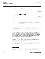
en06000595.vsd
Fw
Rv
-jX
C
Fw
Rv
-jX
C
Fw
Rv
-jX
C
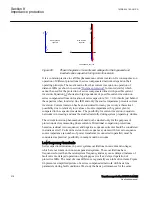
IEC06000595 V1 EN-US
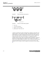
Figure 88:
Thyristor switched series capacitor
en06000596_ansi.vsd
-jX
C
Fw
Rv
jX
L
i
L
i
V
V
C
+
-
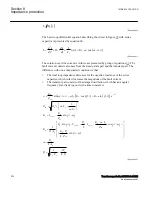
ANSI06000596 V1 EN-US
Figure 89:
Thyristor controlled series capacitor
I
L
Line current
I
V
Current through the thyristor
U
C
Voltage over the series capacitor
X
C
Rated reactance of the series capacitor
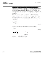
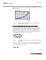
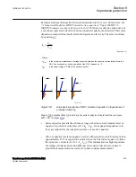
A thyristor controlled series capacitor (TCSC) allows continuous control of the series
capacitor reactance. This is achieved by adding current through the capacitor via the
parallel thyristor valve path see figure
. The main circuit of the TCSC consists of a
capacitor bank and a thyristor controlled inductive branch connected in parallel. The
capacitor bank may have a value of for example, 10...30 Ω/phase and a rated
continuous current of 1500...3000 A. The capacitor bank for each phase is mounted on
a platform providing full insulation towards ground. The thyristor valve contains a
string of series connected high power thyristors with a maximum total blocking voltage
in the range of hundreds of kV. The inductor is an air-core reactor with a few mH
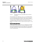
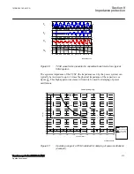
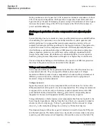
inductance. The wave forms of a TCSC in capacitive boost mode are shown in figure
Section 8
1MRK 504 163-UUS A
Impedance protection
212
Transformer protection RET670 2.2 ANSI
Application manual
Summary of Contents for RELION RET670
Page 1: ...RELION 670 SERIES Transformer protection RET670 Version 2 2 ANSI Application manual ...
Page 2: ......
Page 48: ...42 ...
Page 64: ...58 ...
Page 74: ...68 ...
Page 104: ...98 ...
Page 194: ...188 ...
Page 518: ...512 ...
Page 618: ...612 ...
Page 648: ...642 ...
Page 666: ...660 ...
Page 672: ...666 ...
Page 682: ...676 ...
Page 844: ...838 ...
Page 868: ...862 ...
Page 956: ...950 ...
Page 964: ...958 ...
Page 1004: ...998 ...
Page 1014: ...1008 ...
Page 1015: ...1009 ...

