


Distributed busbar protection REB500
1MRK 505 352-BEN
Product version: 8.2
Issued: 2016-03-01
Revision: -
12
ABB
5. Functionality
Busbar protection
The protection algorithms are based on two well-proven
measuring principles which have been applied
successfully in earlier ABB low-impedance busbar
protection systems:
a) Stabilized differential current measurement
principle
b) Phase comparison measurement principle
The algorithms process complex current vectors which are
obtained by Fourier analysis and only contain the
fundamental frequency component. Any DC component
and harmonics are suppressed.
Stabilized differential current measurement
The first measuring principle uses a stabilized differential
current algorithm. The currents are evaluated individually
for each of the phases and each section of a busbar
(protection zone).
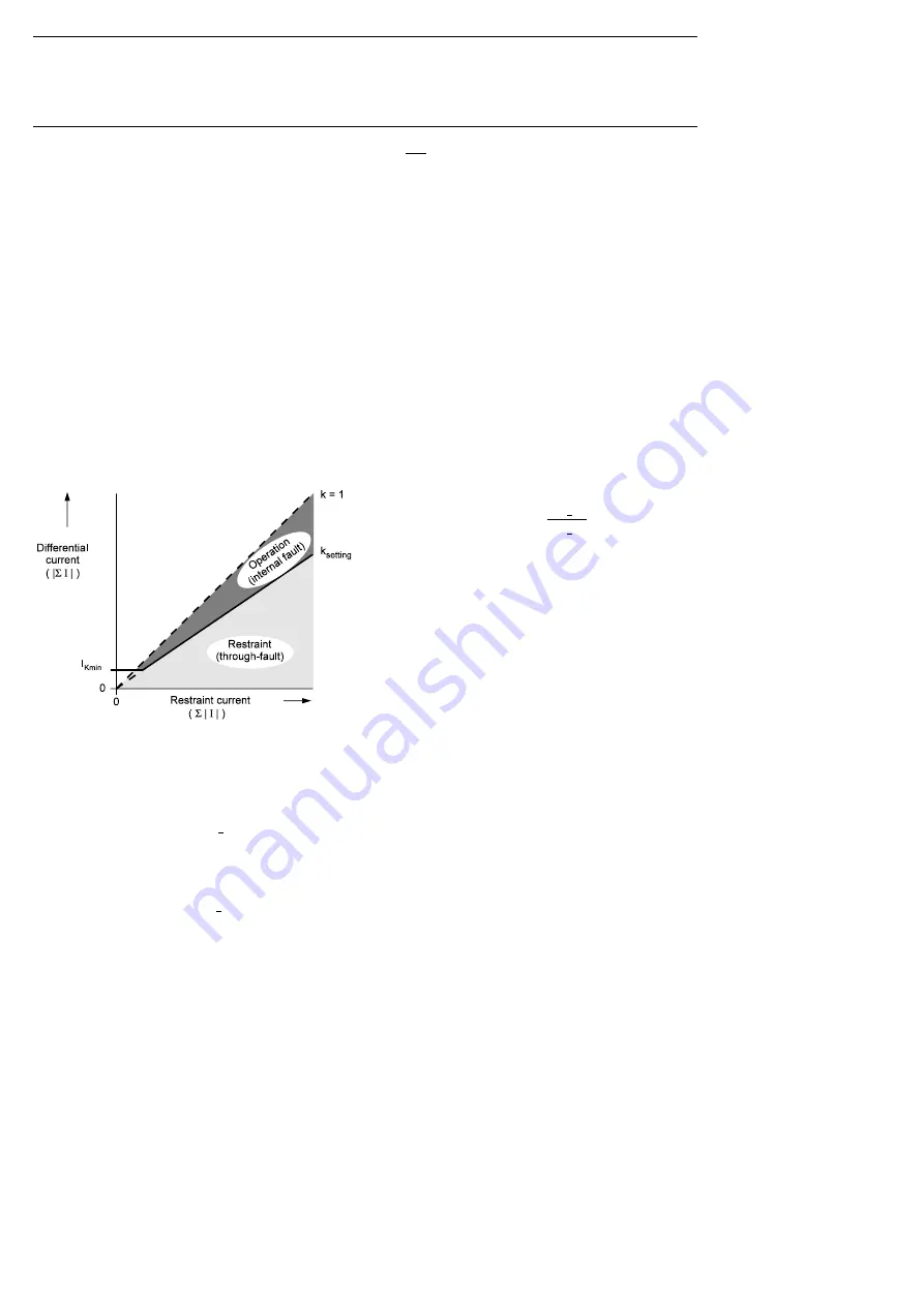
Figure 9. Tripping characteristic of the stabilized
differential current algorithm
In Figure 9, the differential current is
=
and the restraint current is
=
where
is the number of feeders.
The following two conditions have to be accomplished for
the detection of an internal fault:
=
>
AND
>
where
stabilizing factor
stabilization factor limit (typically 0.80)
differential current pick-up value
The above calculations and evaluations are performed by
the central unit.
Phase comparison
The second measuring principle determines the direction
of energy flow and involves comparing the phases of the
currents of all the feeders connected to a busbar section.
The fundamental frequency current phasors
, … ,
are
compared. In the case of an internal fault, all of the feeder
currents have almost the same phase angle, while in
normal operation or during an external fault at least one
current is approximately 180° out of phase with the others.
= arctan
Im
( )
Re
( )
The algorithm detects an internal fault when the difference
between the phase angles of all the feeder currents lies
within the tripping angle of the phase comparator (see
Figure 10).
Processing
The task of processing the algorithms is shared between
the bay units and the central processing unit. Each of the
bay units continuously monitors the currents of its own
feeder, preprocesses them accordingly and then filters the
resulting data according to a Fourier function. The analog
data filtered in this way is then transferred at regular
intervals to the central processing unit running the busbar
protection algorithms.
Depending on the phase-angle of the fault, the tripping
time at
/
,
≥
5
is typically 15 ms including the
auxiliary tripping relay.
Optionally, the tripping signal can be interlocked by a
current or voltage release criterion in the bay unit that
enables tripping only when a current above a certain
minimum is flowing, or the voltage is below a certain
value, respectively.
Summary of Contents for Relion REB500
Page 1: ...Relion Distributed busbar protection REB500 Product Guide...
Page 49: ......