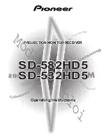
bus depending on type of overvoltage protection used on capacitor bank (spark gap
or MOV) and SC location on protected power line.
en06000612.vsd
~
E
A
0%
33 %
50 %
66 %
K
C =
80%
33%
33 %
50 %
Z<
100 %
80 %
IEC06000612 V1 EN-US
Figure 86:
Typical locations of capacitor banks on series compensated line
Implementation of spark gaps for capacitor overvoltage protection makes the
picture relatively simple, because they either flash over or not. The apparent
impedance corresponds to the impedance of non-compensated line, as shown in
figure
case K
C
= 0%.
en06000613.vsd
jX
R
KC = 0%
KC = 80%
LOC = 0%
KC = 50%
LOC = 50%
jX
jX
R
R
KC = 2 x 33%
LOC = 33%, 66%
KC = 80%
LOC = 100%
jX
jX
R
R
IEC06000613 V1 EN-US
Figure 87:
Apparent impedances seen by distance IED for different SC
locations and spark gaps used for overvoltage protection
Section 8
1MRK 506 369-UEN B
Impedance protection
178
Line distance protection REL670 2.2 IEC
Application manual
Summary of Contents for REL670 2.2 IEC
Page 1: ...RELION 670 SERIES Line distance protection REL670 Version 2 2 IEC Application manual ...
Page 2: ......
Page 32: ...26 ...
Page 70: ...64 ...
Page 110: ...104 ...
Page 152: ...146 ...
Page 564: ...558 ...
Page 570: ...564 ...
Page 592: ...586 ...
Page 706: ...700 ...
Page 804: ...798 ...
Page 848: ...842 ...
Page 860: ...854 ...
Page 882: ...876 ...
Page 896: ...890 ...
Page 906: ...900 ...
Page 907: ...901 ...