background image

D. Circuit breaker operation

The breaker contact status is indicated by the handle 
position, and the positions are marked on either side 
of the handle escutcheon, clearly showing the status of 
the breaker contacts.  ON and/or I indicate breaker is 
ON and OFF 
and/or O indicate breaker is OFF.  
The breaker tripped position  
is indicated by the symbol

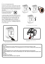
To close the breaker from the OFF position move the 
handle to the ON position. To close the breaker from 
the trip position, first move the handle fully to the 
OFF (reset) position then to the ON position.  See 
Figure 4. A 

Push-To-Trip

 button is provided for 

convenience of testing the mechanical trip operation 
of the breaker, see Figure 3. The 

Push-To-Trip

 should 

be tested annually. 

ON

II

O

O

TRIPPED

OFF

3

Fig 3. Circuit


 Breaker Push-To-trip 

Fig 4. Mechanical Operation of the Circuit Breaker

Fig 5. Terminate


 wire as shown (For FBL type 

circuit breakers)

Fig 3. Note
Push to trip operation is same on all the three  versions of the breaker (1pole, 2pole & 3 pole)

L'action "Pousser pour  declencher" est  identique pour  les  trois versions  de  disjoncteurs (1pole, 2poles, 

3poles)

Fig 4. Note
Mechanical operation is same on all the three versions of the breaker (1pole, 2 pole & 3 pole) 

L'action mecanique "ouvrir / fermer" est identique pour les trois versions de disjoncteurs (1pole, 2 poles, 

3poles)
Fig 5. Note
Terminate wire - FBL type

Raccordement des conducteurs pour le type FBL.

Summary of Contents for Record Plus FB100

Page 1: ... of applications All Record Plus TM circuit breakers are listed by Underwriters Laboratories to UL489 stand ard and by the CSA Standard C22 2 No 5 Record Plus TM circuit breakers are designed and manufactured to exceed our global customers high standards for performance reliability and quality Warning DANGER of Electrical shock or injury Ensure ALL electrical power supplies are OFF before installi...

Page 2: ...mm 0 98 in B 98 1mm 3 86 in G 15 0mm 0 59 in C 15 0mm 0 59 in H 70 0mm 2 76 in D 129 7mm 5 11 in J 10 0mm 0 39 in E 17 5mm 0 69 in K 25 4mm 1 00 in Dimension for drill pattern escutcheon Fig 1 c 1 pole A 127 3mm 5 00 in F 5 1mm 0 20 in B 98 1mm 3 86 in G 15 0mm 0 59 in C 15 0mm 0 59 in H 70 0mm 2 76 in D 129 7mm 5 11 in J 10 0mm 0 39 in E 34 9mm 1 38 in K 25 4mm 1 00 in C Wire Terminal Connections...

Page 3: ...d for convenienceof testing the mechanical trip operation of the breaker see Figure 3 The Push To Trip should be tested annually ON I I O O TRIPPED OFF 3 Fig 3 Circuit BreakerPush To trip Fig 4 Mechanical Operation of the Circuit Breaker Fig 5 Terminate wire as shown For FBL type circuit breakers Fig 3 Note Push to trip operationis same on all the three versionsof the breaker 1pole 2pole 3 pole L ...

Page 4: ...s read the accompanying accessory installation instruction and follow carefully all cautions and warnings Fig 6 Typical Accessories See Buylog for Details 4 1SQC930037M0201 DEH41073 February 2020 ABB Inc 305 Gregson Drive Cary NC 27511 electrification us abb com We reserve the right to make technical changes or modify the contents of this document without prior notice With regard to purchase order...

Reviews: