


Section-2
04-3004_S2_OPM_ABB_POWERSCALE_10-50kVA_EN_150113.doc
Page 14/15 ABB
Printed in Switzerland
– Modifications reserved
F1
Battery Fuses
1
4
3
2
6
5
NW24170 (10Kkw)
NW24172 (20kw)
Filter Board
PE
3N
3L3
3L2
3L1
PE
1N
1L3
1L2
1L1
FA6
FA8
FA10
FX1
FA15
FA17
FA19
FX2
-
N
+
FA21
FA20
FA22
2L3
2L2
2L1
2N
FA23
FA24
FA25
PE
FA7
FA9
FA11
Line for
single input
feed
Line for
dual input
feed
FA2
FA3
FA4
Battery Line Fuses
32 A (10 kW)
50 A (20 kW)
CN2
(NW24080)
Pag.3
Only with Parallel option
Internal Battery
Neutral
Battery Input
(Ba/-400VDC)
FA
?
FA14
FA16
FA18
Neutral
Neutral
IA1
Service Bypass
1
2
3
4
14
13
5
6
Load Output
(400VAC)
Rectifier & Bypass
Mains
(Reseux 400VAC)
Battery
Rectifier Line Fuses
32 A (10 kW)
40 A (20KW)
FA1
2
1
4
3
6
5
8
7
Output Switch
OT25 32A (10-20kW)
IA2
2
1
4
3
5
6
14
13
7
8
R
R
R
R
R
R
R
R
R
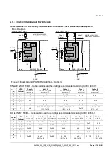
IMPORTANT:
Do not use
Internal and external
batteries in parallel
a)
a)
a)
a)
Link for external
battery
check bag with
accessories
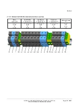
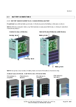
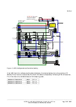
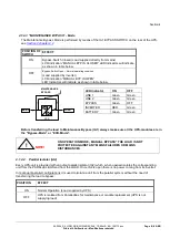
Figure. 5 UPS Configuration with external battery
If the UPS has to be configured with external batteries, the internal battery link to the position of F1
(Battery Fuse) has to be replaced by the short Links delivered separately at the bag of the accessories.
The 3 links has to be installed between the following points.
NW24170 / NW 24172
FA21
F1 / 2
NW24170 / NW 24172
FA20
F1 / 4
NW24170 / NW 24172
FA22
F1 / 6


