


Section-2
04-3004_S2_OPM_ABB_POWERSCALE_10-50kVA_EN_150113.doc
Page 2/15 ABB
Printed in Switzerland
– Modifications reserved
2.1
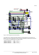
BLOCK DIAGRAM
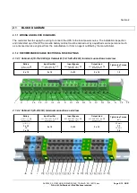
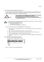
2.1.1 WIRING AND BLOCK DIAGRAMS
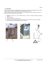
The customer has to supply the wiring to connect the UPS to the local power source. The installation inspection
and initial start up of the UPS and extra battery cabinet must be carried out by a qualified service personnel such
as a licensed service engineer from the manufacturer or from an agent certified by the manufacturer.
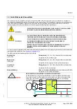
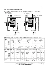
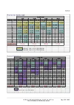
2.1.2 RECOMMENDED CABLE SECTIONS & FUSE RATINGS
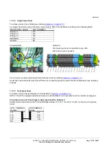
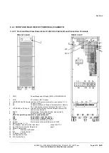
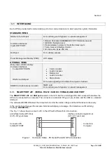
2.1.2.1 Cabinet A (10-15-20 kVA) & Cabinet B (10-15-20-25 kVA) terminal connections overview
Battery
(+ / N / - ) + PE
[quantity x mm
2
]
Input Rectifier
1L1, 1L2, 1L3 + N + PE
[quantity x mm
2
]
Input Bypass
2L1, 2L2, 2L3 + N + PE
[quantity x mm
2
]
Output load
3L1, 3L2, 3L3 + N + PE
[quantity x mm
2
]
Tightening Torque
[Nm]
4 x 16
5 x 16
5 x 16
5 x 16
1.5
+
N
-
PE
PE
1L1
1L2
1L3
N
2L1
2L2
2L3
N
3L1
3L2
3L3
N
PE
PE
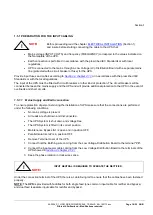
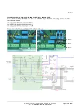
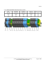
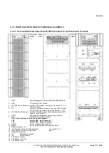
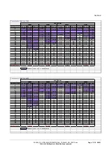
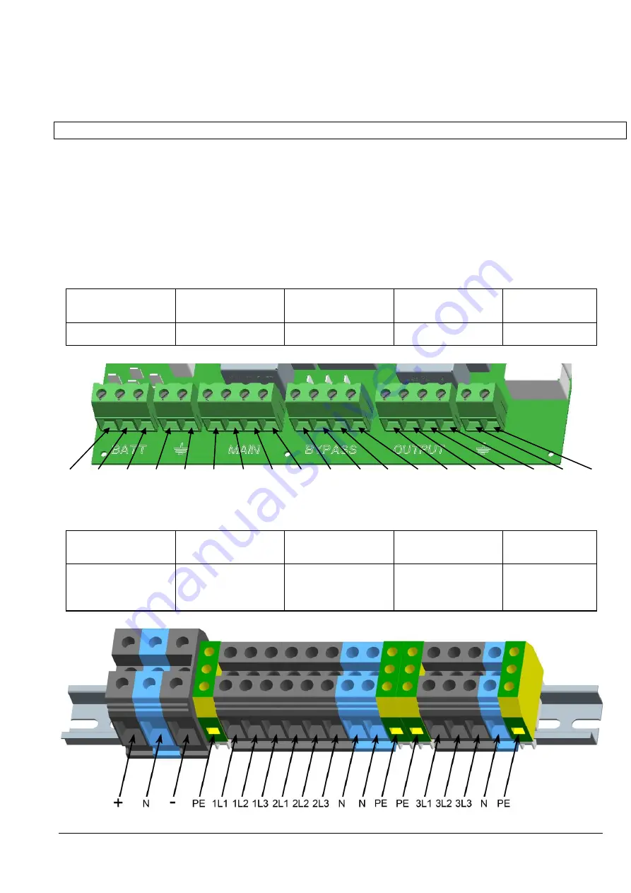
2.1.2.2 Cabinet C (25-30 kVA) terminal connections overview
Battery
(+ / N / - ) + PE
[quantity x mm
2
]
Input Rectifier
1L1, 1L2, 1L3 + N + PE
[quantity x mm
2
]
Input Bypass
2L1, 2L2, 2L3 + N + PE
[quantity x mm
2
]
Output load
3L1, 3L2, 3L3 + N + PE
[quantity x mm
2
]
Tightening Torque
[Nm]
(+ / N / - ):
3 x 35
PE:
1 x 16
5 x 16
5 x 16
5 x 16
35 mm
2
:
3.5
16 mm
2
:
1.5


