ABB OMD800 Installation And Operating Instruction Download Page 67

67

AUTOM ATIC CONTROL U N IT, OM D8 0 0

AU TO M AT I C  CO N T R O L  U N I T,  O M D 8 0 0
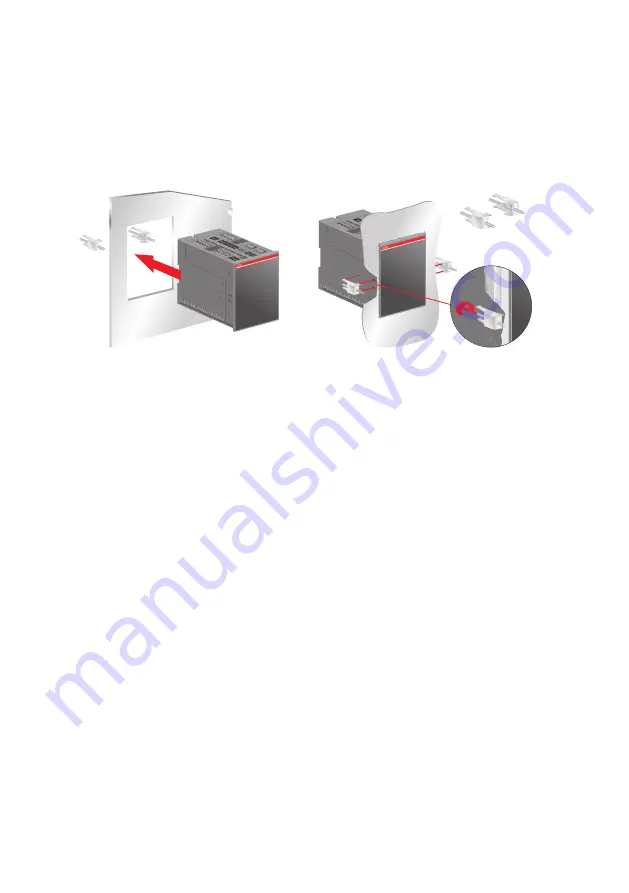
Figure 10.1 

Fastener OMZD1, used when the automatic control unit OMD800 is mounted on the door

OMD

OMD

OMZD1

×2

K

A00

326

2

1

2b

2a

10 Accessories


10.1  

Fastener

Summary of Contents for OMD800

Page 1: ... INSTALL ATION AND OPER ATING INSTRUCTION Automatic control unit OMD800 Automatic control unit 34OOMS800 rev E 1SCC390126M0202 ...

Page 2: ...AUTOMATIC CONTROL UNIT OMD800 ...

Page 3: ...Manual back switching mode 12 4 Installation 13 4 1 Dimensional drawings 13 4 2 Mounting 14 4 2 1 Door mounting 14 15 4 2 2 DIN rail mounting 16 17 5 Connecting 18 5 1 Power circuit 18 5 2 Control circuit 19 5 2 1 Control circuit diagram OMD800 with motorized OTM40 125_CMA_ 19 5 2 2 Control circuit diagram OMD800 with motorized OTM160 2500_CM_ 20 21 5 2 3 OMD800 outputs 22 5 2 4 OMD800 inputs 22 6...

Page 4: ...Menu browsing keys 28 7 2 2 Display 29 53 7 2 3 OMD800 communication via Modbus 53 61 8 Technical data of the automatic control unit OMD800 62 9 Troubleshooting OMD800 63 65 9 1 Explanations of internal faults OMD800 66 9 2 Change over switch does not respond 66 9 3 Missing of both lines 66 10 Accessories 67 10 1 Fastener 67 10 2 Cover plate 68 69 ...

Page 5: ...o a person or damage to equipment Information provides important information about the equipment 1 2 Explanations of abbreviations and terms 1 1 Use of symbols OMD The control unit of automatic transfer switching equipment common type name for the automatic control unit OMD800 The automatic control unit high version with communication and display DPS Modbus RTU Dual power source Bus communication ...

Page 6: ...onfiguration and control are possible via Modbus RTU connection The OMD800 has a graphic display where the user is able to check the settings and get all the information about status of the OMD800 Analysing the voltage frequency and the phase balance Includes the generator START STOP command Communication via Modbus DI DO Figure 2 1 Automatic control unit OMD800 1 User interface consists of displa...

Page 7: ...ains Generator line B Mains a Mains b In case of loss of the primary power line the OMD800 device manages the switching to a secondary power line used as an emergency source Figure 2 3 Mains a Mains b Automatic control unit type OMD800 is designed for single and three phase distribution systems in diverse applications OMD800 is supplied from Line 1 and Line 2 and can be used without external power...

Page 8: ... not Figure 2 6 The circuit diagram when N line is not connected Figure 2 5 An external 24 110 Vdc auxiliary power supply LINE 1 LINE 2 L1 L2 N L3 1 4 3 2 LN1 L1 L2 N L3 X11 L1 L2 N L3 X12 1 4 3 2 LN2 L1 L2 N L3 KA00426 LINE 1 LINE 2 N L1 1 4 3 2 L1 N X11 L1 N X12 1 4 3 2 L1 N KA00425 LINE 1 LINE 2 L1 L2 N L3 1 4 3 2 LN1 L1 L2 N L3 X11 L1 L2 N L3 X12 1 4 3 2 LN2 L1 L2 N L3 KA00466 1 2 X41 AUX LINE...

Page 9: ...l output off And the back switching sequence can be summarized in the following steps The Line 1 will start the normal functioning Back switching delay If Pre transfer signal active Pre transfer output on Pre transfer II to I delay Change over switch Switch II to the position O Dead band II to I delay Change over switch Switch I to the position I If Pre transfer signal active Pre transfer output o...

Page 10: ...g sequence can be summarized in the following steps The Line 1 will start the normal functioning An anomaly occurs on the Line 2 Switching delay If Pre transfer signal active Pre transfer output on Pre transfer II to I delay Change over switch Switch II to the position O Dead band II to I delay Change over switch Switch I to the position I If Pre transfer signal active Pre transfer output off Gene...

Page 11: ...arized in the following steps The Line 2 will start the normal functioning Back switching delay If Pre transfer signal active Pre transfer signal output on Pre transfer I to II delay Change over switch Switch I to the position O Dead band I to II delay Change over switch Switch II to the position II If Pre transfer signal active Pre transfer signal output off Figure 3 3 Automatic Switching Sequenc...

Page 12: ...transfer I to II delay Change over switch Switch I to the position O Dead band I to II delay Change over switch Switch II to the position II If Pre transfer signal active Pre transfer signal output off And the back switching sequence can be summarized in the following steps The Line 1 will start the normal functioning Back switching delay Change over switch stays in position II An anomaly occurs o...

Page 13: ...13 AUTOMATIC CONTROL UNIT OMD800 4 Installation 4 1 Dimensional drawings Figure 4 1 OMD800 dimensions of the device 160 KA00480 91 139 2 OMZD1 2 1 2b 2a ...

Page 14: ...with the fastener OMZD1 see Acces sories Section 10 Door drilling according to Figure 4 2 As an optional extra you can use the cover plate OMZC2 on the door for OMD800 see Figure 4 3 on next page and Accessories Section 10 Figure 4 2 Automatic control unit OMD800 door mounting door drilling 160 KA00480 91 139 2 OMZD1 2 1 2b 2a ...

Page 15: ... OMD800 OMD A07227 OMD OMD OMZC2 OMZD1 4 3 2 1 3 5 8 TX15 0 8 Nm 8 OMD OMZD1 2 4b 4a Figure 4 3 Automatic control unit OMD800 door mounting with the cover plate door drilling for the cover plate OMZC2 see Accessories Section 10 ...

Page 16: ...m DIN rail see the Figure 4 4 Door drilling if needed according to Figure 4 4 As an optional extra you can use the cover plate OMZC2 on the door for OMD800 see Figure 4 5 and Accessories Section 10 Figure 4 4 Automatic control unit OMD800 DIN rail mounting door drilling A07291 35 mm EN 50022 3 2 1 97 145 Remove 1 2 3 ...

Page 17: ...C CONTROL UNIT OMD800 Figure 4 5 Automatic control unit OMD800 DIN rail mounting with the cover plate door drilling for the cover plate OMZC2 see Accessories Section 10 OMZC2 A07268 OMD OMD 2 3 5 8 TX15 0 8 Nm 8 1 ...

Page 18: ...that the switch is de energised 5 1 Power circuit Operating and measuring voltage area on 3 phase system Main voltage 100 Vac 480 Vac 20 Phase voltage 57 7 Vac 277 Vac 20 AUX voltage 24 Vdc 110 Vdc 10 to 15 Frequency 50 Hz 60 Hz 10 Operating and measuring voltage area on 1 phase system Phase voltage 57 7 Vac 240 Vac 20 AUX voltage 24 Vdc 110 Vdc 10 to 15 Frequency 50 Hz 60 Hz 10 Phase setting see ...

Page 19: ...19 AUTOMATIC CONTROL UNIT OMD800 Figure 5 1 Control circuit diagram OMD800 with motorized OTM40 125_CMA_ A07290 5 2 Control circuit 5 2 1 Control circuit diagram OMD800 with motorized OTM40 125_CMA ...

Page 20: ...20 AUTOMATIC CONTROL UNIT OMD800 Figure 5 2 Control circuit diagram OMD800 with motorized OTM160 2500_CM_ 5 2 2 Control circuit diagram OMD800 with motorized OTM160 2500_CM_ A07276 ...

Page 21: ... OMD800 Figure 5 3 Connectors OMD800 Con nec tor Description X29 1 X29 2 X29 3 X29 4 X29 5 X29 6 X29 7 Emergency Alarm NO Programmable Line I Status NO Programmable Line II Status NO Programmable Change over Switch Alarm NO Programmable Manual Mode NO Programmable Disconnect Secondary Loads NO Programmable Common X31 1 X31 2 X31 3 X31 4 Manual Alarm input from handle Status of switch I auxiliary c...

Page 22: ...d to secondary loads X24 DO11 See Secondary Load parameter Section 7 2 2 3 5 2 3 4 Programmable digital outputs X29 DO6 DO10 and DO12 These outputs can be configured by the user User can choose the function and the contact type for each of these outputs For configuration see Section 7 2 2 3 Default configuration is shown in Section 5 2 2 Table 5 1 5 2 4 OMD800 inputs 5 2 4 1 Switch status input X3...

Page 23: ...ient caution when handling the unit 6 1 Automatic control unit OMD800 in Manual Mode Selecting the automatic control unit OMD800 to the Manual Mode a Make sure that power LED is ON see the Figure 4 1 j b If Auto LED is OFF k the automatic control unit is in Manual Mode c If the Auto LED is ON push the AUTO key once l The Auto LED switches to OFF and the automatic control unit OMD800 is in Manual M...

Page 24: ...n see the Figure 6 2 l and the II switch will be in the OFF position If the I switch is already in the ON position pushing the I key does not have any influence c When pushing the O key the I switch will be in the OFF position The II switch remains in the OFF position d When pushing the II key the II switch will be in the ON position and the I switch will be in the OFF position e If you push the I...

Page 25: ...r command I or II the motorized change over switch OTM_C is driven to the position O 6 2 Automatic control unit OMD800 in Automatic mode A07278 OR Automatic mode 1 2 1 OFF I ON II ON 3 Automatic mode I I II OMD OFF ON I ON I I II OMD OFF ON I ON I I I II OMD OFF ON I ON I position 0 position II position A07279 I command II command 0 command I ON II ON II ON O OFF O OFF II 0 Selecting the automatic...

Page 26: ...n in manual and auto mode both switches I and II are in the OFF position After pressing the O key the automatic control unit OMD800 is always in manual mode I key Setting in manual mode the motorized change over switch OTM_C to position I when the I switch will be in the ON position and the II switch will be in the OFF position II key Setting in manual mode the motorized change over switch OTM_C t...

Page 27: ...st one minute after power failure A blinking Power LED indicates standby mode Tx Rx A green Tx Rx LED signals the state of communication bus When the LED is blinking the automatic control unit OMD800 is sending data to the bus Alarm A red Alarm LED signals an external alarm Alarm status is explained in the Table 7 1 An active alarm is set off by pushing the AUTO key KA00298 Figure 7 3 LEDs on OMD8...

Page 28: ... control unit OMD800 from the display The default password is 0001 7 2 Configuration 7 2 1 Menu browsing keys Enter is used to enter a new menu page and to accept function ECS is used to exit a menu page UP is used to move one step up on the menu DOWN is used to move one step down on the menu ...

Page 29: ...e of voltage on the line is under 10 of the Rated Voltage 2 Undervoltage Value of voltage is under defined settings 3 Overvoltage Value of voltage is over defined settings 4 Phase missing There is one or more phases missing 5 Voltage unbalance Difference between lowest and highest phase voltage is higher than defined setting 6 Incorrect phase sequence Order of phases is incorrect 7 Invalid frequen...

Page 30: ... the configuration subpages Figure 7 7 The Default pages show the status of secondary load open or closed When Secondary Load parameter is set to Opening Only or Opening and Closing the status of the device used for controlling the secondary load is shown on the default page Please notice that the status open closed of the secondary load controlling device on the display is related to the status o...

Page 31: ...13 A07133 System Configuration Changeover Switch Type Manual Back Switching Generator Shutdown 13 13 A07135 Table 7 3 Parameters and values of the System Configuration Parameter Values Rated Voltage 100 57 V 115 66 V 120 70 V 208 120 V 220 127 V 230 132 V 240 138 V 277 160 V 347 200 V 380 220 V 400 230 V 415 240 V 440 254 V 480 277 V Rated Frequency 50 Hz and 60 Hz Number of Phases LN1 3 phases wi...

Page 32: ...phases with N is the default Number of Phases LN2 In Line 2 user can choose between a one phase and a three phase system with or without N Three phase system with N is the default Figure 7 13 Number of phases LN2 3 phases with N is the default Rated Voltage KA00260 400 230 V Cancel Edit OK Rated Frequency KA00261 50 Hz Cancel Edit OK System Configuration Rated Voltage Rated Frequency Number of Pha...

Page 33: ... secondary voltage of the external voltage transformer Secondary voltage is set according to transformer ratio Factory setting is 400 230 V Figure 7 16 Ext VT Secondary Voltage factory setting is 400 230V System Configuration Number of Phases LN1 Number of Phases LN2 Ext Voltage Transformer 5 13 A07122 Ext Voltage Transformer Absent A07123 Cancel Edit OK System Configuration Number of Phases LN2 E...

Page 34: ... 2 Switch II When generator is in use line priority can t be set to value Line 2 LN 2 Switch II X24 Switch II auxiliary contact Secondary load S07225 Output relay X24 see control circuit diagram Section 5 2 operates in two cases 1 Secondary Load parameter value is Opening Only or Opening Pulse and OMD800 automatic control unit performs switching sequence 2 Secondary Load parameter value is Opening...

Page 35: ...ator alarm If the Generator Shutdown is set to On the generator stop command will be sent im mediately after receiving the generator alarm In this case also back switching delay is overridden and the back switching to Line 1 will take place immediately If the Line 1 is not available the switch will change to position O If the Generator Shutdown is set to Off loads are supplied from generator line ...

Page 36: ...umbers it is given by UP DOWN and ENTER keys The default password is 0001 Please change the default password to your own The password is valid one minute after leaving the password protected subpage If the password is forgotten or lost please contact product support Device Configuration Digital Inputs Digital Outputs Voltage Tresholds 2 12 A07142 Device Configuration Voltage Hysteresis Frequency T...

Page 37: ...sis Max LN1 4 5 29 Volt Hysteresis Max LN2 4 5 29 Frequency Thresholds Freq Threshold Min LN1 10 9 1 Freq Threshold Min LN2 10 9 1 Freq Threshold Max LN1 1 2 10 Freq Threshold Max LN2 1 2 10 Frequency Hysteresis Freq Hysteresis Min LN1 9 8 9 6 0 8 Freq Hysteresis Min LN2 9 8 9 6 0 8 Freq Hysteresis Max LN1 0 8 1 0 9 8 Freq Hysteresis Max LN2 0 8 1 0 9 8 Delay Times Switching 0 60 s Delay on Transf...

Page 38: ...CHANGED Digital Inputs User can configure Function and Contact Type NO NC for Digital Inputs 4 11 Available functions are described in Table 7 5 Factory settings are described in Section 2 1 Digital Inputs Digital Input 4 Digital Input 5 Digital Input 6 1 8 A07137 Device Configuration Digital Inputs Digital Outputs Voltage Tresholds 1 12 KA00272 Figure 7 24 Digital Inputs user can configure Functi...

Page 39: ...rce switching from primary to secondary line in AUTO mode External generator start Digital input to start generator externally Status of secondary loads Digital input to connect feedback from secondary loads control device Manual back switching mode Digital input to prevent automatic switching to primary line Remote reset Digital input to reset active alarm Line Priority I Digital input to set pri...

Page 40: ...s communication interface This way user can have different loads which can be controlled independently via Modbus communication interface Function Description No function Digital output disabled Emergency alarm Digital output to signal changeover switch control failure handle attached external fault or generator alarm Line I status Digital output to signal status of the Line 1 Line II status Digit...

Page 41: ...ontact type NO Contact type NC Function Function status Contact status No function Digital output disabled Emergency alarm Emergency alarm ON Closed Open Emergency alarm OFF Open Closed Line 1 status Line 1 status OK Open Closed Line 1 status NOT OK Closed Open Line 2 status Line 2 status OK Open Closed Line 2 status NOT OK Closed Open Change over switch alarm Change over switch alarm ON Closed Op...

Page 42: ...274 Volt Treshold Min LN1 20 KA00330 Cancel Edit OK Voltage Tresholds Volt Treshold Min LN1 Volt Treshold Min LN2 Volt Treshold Max LN1 3 4 A07151 Volt Treshold Max LN1 20 KA00331 Cancel Edit OK Figure 7 31 Voltage Threshold LN1 factory settings min 20 max 20 Device Configuration Digital Inputs Digital Outputs Voltage Tresholds 3 12 A07148 3 phases Voltage V Voltage threshold Min Max 100 57 115 66...

Page 43: ...ration Digital Outputs Voltage Tresholds Voltage Hysteresis 4 12 A07154 Figure 7 34 Interaction of the parameters Voltage Threshold and Voltage Hysteresis Volt Threshold Max Volt Hysteresis Max Volt Hysteresis Min Volt Threshold Min Line ok Line not ok A07293 Voltage Hysteresis User can set separately Line 1 and Line 2 voltage hysteresis both minimum and maximum values Factory settings are min 19 ...

Page 44: ...esholds Voltage Hysteresis Frequency Tresholds 5 12 A07163 Frequency Thresholds Freq Threshold Min LN2 Freq Threshold Max LN1 Freq Threshold Max LN2 4 4 A07167 Frequency Thresholds Freq Threshold Min LN1 Freq Threshold Min LN2 Freq Threshold Max LN1 1 4 KA00275 Frequency Thresholds Freq Threshold Min LN1 Freq Threshold Min LN2 Freq Threshold Max LN1 3 4 A07166 Frequency Thresholds Freq Threshold M...

Page 45: ...uency Hysteresis Freq Hysteresis Min LN2 Freq Hysteresis Max LN1 Freq Hysteresis Max LN2 4 4 A07176 Frequency Hysteresis Freq Hysteresis Min LN1 Freq Hysteresis Min LN2 Freq Hysteresis Max LN1 1 4 A07170 Freq Hysteresis Min LN1 0 8 A07171 Cancel Edit OK Frequency Hysteresis Freq Hysteresis Min LN1 Freq Hysteresis Min LN2 Freq Hysteresis Max LN1 3 4 A07174 Freq Hysteresis Max LN1 0 8 A07175 Cancel ...

Page 46: ...l Edit OK Back Switching KA00412 0 s Cancel Edit OK Generator Stop 5 s KA00413 Cancel Edit OK Device Configuration Frequency Tresholds Frequency Hysteresis Delay Times 7 12 A07115 Delay Times Switching Delay on Transfer Dead Band I to II 1 6 KA00276 Switching KA00409 0 s Cancel Edit OK The switching sequence and the operation of corresponding Delay Times are shown in Section 3 1 Delay Times User c...

Page 47: ... to position O in case of Line 1 or Line 2 anomaly Table 7 9 Values and description of Auto Switch to O LCD Backlight Timer User can choose when to switch off the LCD backlight after the latest user interaction Device Configuration Frequency Hysteresis Delay Times Auto Switch to 0 8 12 A07183 Auto Switch to 0 Off A07184 Cancel Edit OK Figure 7 41 Auto Switch to O Off is the default Device Configur...

Page 48: ...ible to control and configure the device through Modbus Available parameter values for Modbus are described in Table 7 10 Factory settings are Modbus address 1 Mod bus Baud Rate 9600 Modbus Stop Bit 1 Modbus Parity None and Modbus Local Remote Local Parameter Value Modbus Address 1 247 Modbus Baud Rate 9600 bps 19200 bps 38400 bps Modbus Stop Bits 1 Stop Bit 2 Stop Bits Modbus Parity None Even Odd...

Page 49: ...ud Rate 9600 bps A07190 Cancel Edit OK Modbus Modbus Address Modbus Baud Rate Modbus Stop Bits 3 5 A07191 Modbus Stop Bits 1 Stop Bit A07192 Cancel Edit OK Modbus Modbus Baud Rate Modbus Stop Bits Modbus Parity 4 5 A07193 Modbus Parity None A07194 Cancel Edit OK Local Remote Local A07195 Cancel Edit OK Modbus Modbus Stop Bits Modbus Parity Local Remote 5 5 KA00279 Figure 7 43 Modbus the factory se...

Page 50: ...Password 12 12 A07197 Change Password KA00280 0001 Back Edit Forward Figure 7 45 Change Password 0001 is the default password Retype New Password The new password has to be confirmed by retyping it After confirmation the user is returned to the Device Configuration menu and on the bottom of the display the message PASSWORD CHANGED is shown If password confirmation does not succeed on the bottom of...

Page 51: ...he both pages Diagnostics Measured Values Alarm Event Log Counters 1 6 KA00281 SW 2A1 SN 0 LN1 f 0 0 Hz UL1 0 0 V UL2 0 0 V UL3 0 0 V Return L L Voltages LN2 f 0 0 Hz UL1 0 0 V UL2 0 0 V UL3 0 0 V KA00329 LN1 f 0 0 Hz UL1 L2 0 0 V UL2 L3 0 0 V UL3 L1 0 0 V Return L N Voltages LN2 f 0 0 Hz UL1 L2 0 0 V UL2 L3 0 0 V UL3 L1 0 0 V KA00337 Figure 7 48 Measured Values Main Voltages with frequency and Ph...

Page 52: ... 6 A07201 SW 2A1 SN 0 Counters KA00402 OPERATIONS 0 Return Figure 7 50 Counters page will show the summary of operations Generator Control On this page the user can start or stop the generator if generator is in use see the selection of Generator Usage in Section 7 2 2 3 Start and Stop commands are given with UP and DOWN arrow keys OMD800 must be on Manual mode when starting the generator manually...

Page 53: ...ndary Loads On this page the user can connect or disconnect the secondary loads if the Secondary Load parameter is set in System Configuration subpage see the selection of Secondary Load on Section 7 2 2 3 Con nect and Disconnect commands are given with UP and DOWN arrow keys Return back to Diagnostics menu by pushing the ESC key Diagnostics Generator Control Test Sequence Secondary Loads 6 6 A072...

Page 54: ... sequence 7 Invalid frequency Bits 3 5 LN2 status 0 Voltage OK 1 No voltage 2 Undervoltage 3 Overvoltage 4 Phase missing 5 Voltage unbalance 6 Incorrect phase sequence 7 Invalid frequency Bits 6 8 Switching status 0 Sequence not required line used primary 1 Sequence in progress primary secondary 2 Sequence completed line used secondary 3 Sequence rev in progress secondary primary 4 Sequence failed...

Page 55: ...TY_I 73 R 0 Inactive 1 Active REG_LINE_PRIORITY_II 74 R 0 Inactive 1 Active REG_EXTERNAL_ALARM 75 R 0 Inactive 1 Active REG_LN1_U1 150 R Voltage at 0 1 V accuracy 2300 230 0 V REG_LN1_U2 152 R Voltage at 0 1 V accuracy 2300 230 0 V REG_LN1_U3 154 R Voltage at 0 1 V accuracy 2300 230 0 V REG_LN1_U12 158 R Voltage at 0 1 V accuracy 2300 230 0 V REG_LN1_U23 160 R Voltage at 0 1 V accuracy 2300 230 0 ...

Page 56: ... 1 Remote REG_ADDRESS 604 R W 1 247 REG_BAUD_RATE 605 R W 0 9600 1 19200 2 38400 REG_PROTOCOL 606 R W 0 Even parity 8 data bits 1 stop bit 1 Odd parity 8 data bits 1 stop bit 2 No parity 8 data bits 1 stop bit 3 Even parity 8 data bits 2 stop bits 4 Odd parity 8 data bits 2 stop bits 5 No parity 8 data bits 2 stop bits REG_TAG_NAME_0 607 R W Letter 0 in ASCII format REG_TAG_NAME_1 608 R W Letter 1...

Page 57: ...Line I Switch 1 2 Line II Switch 2 REG_LANGUAGE 629 R W 0 English 1 German 2 French 3 Italian 4 Spanish 5 Finnish 6 Russian 7 Chinese REG_PASSWORD 630 R W 0000 9999 REG_EXT_VT_PRESENT 631 R W 0 Absent 1 Present REG_EXT_VT_PRIMARY 632 R W 0 100 57 V 1 115 66 V 2 120 70 V 3 208 120 V 4 220 127 V 5 230 132 V 6 240 138 V 7 277 160 V 8 347 200 V 9 380 220 V 10 400 230 V 11 415 240 V 12 440 254 V 13 480...

Page 58: ...otorized OTM_C REG_DI4_FUNCTION 639 R W 0 No function 1 Emergency stop 2 Inhibit switching I to II 3 Remote control to O 4 Remote control to I 5 Remote control to II 6 Inhibit remote control 7 Generator alarm 8 Force commutation 9 External generator start 10 Status of secondary loads 11 Manual back switching mode 12 Remote reset 13 Line priority I 14 Line priority II 15 External alarm REG_DI5_FUNC...

Page 59: ...TION 659 R W See REG_DO6_FUNCTION values REG_DO12_FUNCTION 660 R W See REG_DO6_FUNCTION values REG_DO6_CONTACT_TYPE 661 R W 0 NO 1 NC REG_DO7_CONTACT_TYPE 662 R W See REG_DO6_CONTACT_TYPE values REG_DO8_CONTACT_TYPE 663 R W See REG_DO6_CONTACT_TYPE values REG_DO9_CONTACT_TYPE 664 R W See REG_DO6_CONTACT_TYPE values REG_DO10_CONTACT_TYPE 665 R W See REG_DO6_CONTACT_TYPE values REG_DO12_CONTACT_TYPE...

Page 60: ...og item 15 REG_ALARM_EVENT_LOG_16 2016 R Alarm Event Log item 16 REG_ALARM_EVENT_LOG_17 2017 R Alarm Event Log item 17 REG_ALARM_EVENT_LOG_18 2018 R Alarm Event Log item 18 REG_ALARM_EVENT_LOG_19 2019 R Alarm Event Log item 19 REG_ALARM_EVENT_LOG_20 2020 R Alarm Event Log item 20 REG_ALARM_EVENT_LOG_21 2021 R Alarm Event Log item 21 REG_ALARM_EVENT_LOG_22 2022 R Alarm Event Log item 22 REG_ALARM_E...

Page 61: ..._EVENT_LOG_44 2044 R Alarm Event Log item 44 REG_ALARM_EVENT_LOG_45 2045 R Alarm Event Log item 45 REG_ALARM_EVENT_LOG_46 2046 R Alarm Event Log item 46 REG_ALARM_EVENT_LOG_47 2047 R Alarm Event Log item 47 REG_ALARM_EVENT_LOG_48 2048 R Alarm Event Log item 48 REG_ALARM_EVENT_LOG_49 2049 R Alarm Event Log item 49 REG_TEST_DAY 7009 R W 1 31 REG_TEST_MONTH 7010 R W 1 12 REG_TEST_YEAR 7011 R W 2011 9...

Page 62: ...easuring voltage area on 1 phase system Phase voltage 57 7 Vac 277 Vac1 20 AUX voltage 24 Vdc 110 Vdc 10 to 15 Frequency 50 Hz and 60 Hz 10 Voltage and frequency sensing precision Voltage 1 Frequency 1 Relay utilization category X21 X22 X24 12 A AC1 250 V 12 A DC1 24 V X23 8 A AC1 250 V 8 A DC1 24 V X29 5 A AC1 250 V 6 A DC1 24 V Over voltage category III Uimp 6 kV IP rating IP40 for the front pan...

Page 63: ... Failure Switching from position O to position I fails After 3 seconds the Alarm LED blinks If the alarm activates again after trying to operate the switch please check that the Motor Manual selector of the change over switch only with motorized change over switches OTM160 2500_CM is in Motor M position and check the fuse F1 of the motor operator 8 Close 2 Failure Switching from position O to posi...

Page 64: ... 24 Sec Loads Closed Secondary loads connected 25 Generator Started Generator start activated 26 Generator Stopped Generator stop activated 27 Handle attached Changeover switch handle mounted 28 Handle Detached Changeover switch handle dismounted 29 Force Commutation On Force commutation signal activated 30 Force Commut Off Force commutation signal inactivated 31 Generator Start On External genera...

Page 65: ...ated 60 External Alarm Signal Off External alarm signal inactivated 61 Table 9 2 Events in OMD800 Some of the events include information about current operating mode or event source Information is presented with a capital letter in brackets after the event Letter Source Description Value M Manual Event initiated by user action in manual mode 1 A Auto Event initiated by automatic switching logic 2 ...

Page 66: ...shing the AUTO key During the back switching sequence similiar transitions will be perfomed from II to O and from O to I possibly activating Open 2 Failure or Close 1 Failure Figure 9 1 Unsuccesful switching sequence Figure 9 2 Succesful switching sequence 9 3 Missing of both lines The missing of both lines is indicated by a blinking Power LED In this case the OMD800 will be in a power saving stat...

Page 67: ...67 AUTOMATIC CONTROL UNIT OMD800 Figure 10 1 Fastener OMZD1 used when the automatic control unit OMD800 is mounted on the door OMD OMD OMZD1 2 KA00326 2 1 2b 2a 10 Accessories 10 1 Fastener ...

Page 68: ...D 2 1 3 5 8 TX15 0 8 Nm 8 OMD OMD 3 OMD Ø 4 mm A07211 A07207 A07209 A07207 A07205 A07205 A07213 A07212 A07208 A07214 56 0 56 0 139 0 168 0 120 0 91 0 Ø 4 0 Figure 10 2 Door drilling and mounting of the cover plate OMZC2 when the automatic control unit OMD800 is mounted on the door ...

Page 69: ...mounting of the cover plate OMZC2 when the automatic control unit OMD800 is mounted on the DIN rail OMZC2 IP54 Ø 4 mm A07211 A07207 A07209 A07207 A07273 A07273 A07213 A07212 A07208 A07214 A07273 2 3 5 8 TX15 0 8 Nm 8 OMD OMD 1 56 0 56 0 139 0 168 0 120 0 91 0 Ø 4 0 ...

Page 70: ...70 AUTOMATIC CONTROL UNIT OMD800 ...

Page 71: ...71 AUTOMATIC CONTROL UNIT OMD800 CZ ...

Page 72: ... Contact us ABB Oy P O Box 622 FI 65101 Vaasa Finland abb com lowvoltage Copyright 2020 ABB All rights reserved Specifications subject to change without notice 34OMD800 rev E 1SCC390126M0202 107 01 2020 ...

Reviews: