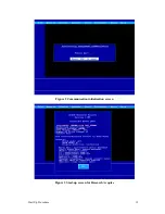
ABB MR Series Startup Procedure Download Page 27


Start-Up Procedure  

21  

c.  HANDLING AND CARE 


The handling and care of the different halide components is not very difficult, but it does require a conscious 
effort to be made by the user to follow the suggested guidelines. Some suppliers of these optical materials had 
been contacted and their procedures for handling of such elements have been reviewed and are restated here for 
clarity. These guidelines, if followed religiously, will help to preserve the optical materials that may be damaged 
so that such materials may be maintained for years without moisture damage. 
The handling and care of the optical materials has been divided into three sub-sections pertaining to care for 
these materials under most conditions, and are as follows: handling, storage, and transport. 

i.  Handling of components 


The handling of materials, that are hygroscopic in nature, must be made with care. The main prerequisite being 
that the environment in which the halide materials are exposed be maintained at less than 35% relative humidity. 
[See Appendix I.4 for discussion of relative humidity.] Do not expose a component whose temperature is below 
that of the ambient temperature, and allow at least 24 hours to ensure that the ambient temperature is reached. In 
general, all storage, installation, and use should be done in a temperature and humidity controlled environment, 
and carried out by qualified personnel familiar with the handling of such components.  

When handling the components, any personnel in contact with the materials should wear a face mask and full 
surgical gloves. This is necessary to avoid the inevitable amounts of moisture that will be present on skin or 
from human breath. Never breathe directly on or near the optical surfaces. Only the outer edge of the material 
should be handled and can be carefully wiped using a clean tissue and isopropyl alcohol to remove any talcum 
powder, lint, finger oils, or moisture that may collect during handling. Note that; unused solvents should be 
discarded as they have a high affinity to absorb water vapor from the air, and, also, materials that are likely to 
absorb moisture (tissues, tape, clothing, etc.) should be removed from close proximity of the optical materials. 

ii.  Storage conditions 

1.  Optical materials 


When the optical materials (that are hygroscopic) are not in use, it is recommended that the components be 
stored in a warm dry place. The relative humidity should always be maintained below at least 35%. [See 
Appendix I-4 for discussion of relative humidity.] The preferred storage location would be a heated desiccator 
cabinet or else an enclosure that is purged with a dry oil free gas (N

2

.) Avoid placing any materials that may 

retain moisture near the optical components or inside the enclosure at all, if possible. The materials may also be 
sealed (airtight) in a plastic storage envelope with a suitable desiccant whose condition should be monitored 
periodically.  

In practice, such cabinets or enclosures and the ability to seal the components are not always readily available. In 
later case, care must be taken to ensure that the optical materials are safely stored. The optical materials can be 
stored in their original shipping containers with suitable desiccant material and heating above ambient 
temperature level.  

Desiccants  

A desiccant is a material that will strongly absorb moisture from the air and can, therefore, minimize the 
atmospheric level of moisture within a confined volume for effectiveness. The desiccant material comes in a 
variety of forms. In environments where the storage location is not well controlled, a desiccant that changes 
color with increasing absorption of water is a very good indicator of humidity levels encountered by the optical 
material. An appropriate amount of desiccant material, usually in a pouch or capsule, should be stored near the 
optical material and this amount will depend on the actual volume and level of dryness required which may vary 
from application to application. A maintenance schedule should be made by the user to observe that the 

Summary of Contents for MR Series

Page 1: ...MR Series FT Spectroradiometers Start Up Procedure This manual contains Information on the unpacking and set up of the MR Series FT Spectroradiometers IMZ8947 Revision 3 1 March 2003 ...

Page 2: ......

Page 3: ...ifications of all equipment and software and contents of this document without obligation to notify any person or organization of such changes Every effort has been made to insure that the information contained in this document is current and accurate However no guarantee is given or implied that the document is error free or that the information is accurate ABB provides product support services t...

Page 4: ......

Page 5: ...HE CONFIGURATION FILE ACQUIRE CFG 16 4 2 1 Changing the instrument type 16 4 2 2 Running Research Acquire without instrument 16 4 2 3 External Trigger address setting 17 5 SHUTDOWN SEQUENCE AND SYSTEM PACKING 17 6 HANDLING AND CARE OF HYGROSCOPIC MATERIALS 19 6 1 INTRODUCTION 19 6 2 HYGROSCOPIC MATERIALS 19 6 3 HANDLING AND CARE 21 6 3 1 Handling of components 21 6 3 2 Storage conditions 21 6 3 2 ...

Page 6: ......

Page 7: ...nt up and running It also contains useful reference information on the set up of the instrument hardware and software and on packing the instrument in order to ship it This section also contains information on the handling of hygroscopic materials and should be studied by customers having ordered optional hygroscopic optics for their MR system ...

Page 8: ......

Page 9: ...G LN2 DETECTOR DEWARS THE MANUAL YOU ARE PRESENTLY READING TRIPOD TRIPOD Upon reception of the material check for any external damage to the carrying cases If any damage is observed please notify the courier and have this stated on the packing slip This is important for making a claim should the equipment have been damaged during shipment Please notify the After Sales Service Department at ABB Bef...

Page 10: ...OPE DETECTOR DETECTOR MEDIUM ANGLE TELESCOPE WIDE ANGLE TELESCOPE CCD CAMERA MONITOR CCD CAMERA POWER SUPPLY CCD CAMERA 90 INPUT COLD SOURCE DATA CABLE SPARE FUNEL MANUALS Computer COMPUTER OR SPARE CABLES MANUALS AND KEY BOARD MOUSE MONITOR COMPUTER OR SPARE COMPUTER OR SPARE BACKUP SOFTWARE MR FT Spectroradiometer SPECTRORADIOMETER Accessories ...

Page 11: ...MR100 In addition to the data connector the resolution setting knob the AC power inlet input power selection on off switch and status LED s can be found on this connector plate The POWER led is always on when the instrument is powered up The other LEDs are used to provide the instrument status during power and operation When the instrument is first turned on the SCAN and DATA LEDs comes on to indi...

Page 12: ...ncy at which the DATA LED s flashes changes accordingly Please note that the data cable can be connected or disconnected at any time whether the unit is turned on or not Doing so will not harm the equipment MR200 connector plate showing fibre optics connector MR200 In addition to the data connector the AC power inlet input power selection on off switch and status display can be found on this conne...

Page 13: ...ion must be clearly defined 7 fringe counter initialisation with ZPD location successful normal scanning ZPD position not same as previous two different consecutive ZPD positions ZPD position not same as previous two different consecutive ZPD positions 8 ZPD located once requires three consecutive identical ZPD positions ZPD located once requires three consecutive identical ZPD positions 9 fringe ...

Page 14: ...iometers 8 MR100 The DSP board occupies two ISA slots in the host computer Only one external connector is available and is used for the connection of the DB 25 serial data cable The board is displayed on the next two figures ...

Page 15: ...t computer Two connectors are available On is used for the connection of the fibre optic data cable The other DB 25 is an unused RS232 port This port could be used to receive RS232 signals coming from an IRIG B time code converter The board is displayed on the next two figures ...

Page 16: ...of the DSP above for their locations on the DSP board You may also perform a visual inspection of the proper insertion of the ISA connector in the slot Should it look outside or not evenly inserted in the slot please push gently on the DSP board making sure that it is well inserted in the slots When the computer is not purchased from ABB the DSP board comes delivered as a separate item To install ...

Page 17: ...he computer and make sure that it boots normally indicating no major hardware problem 12 At this point the computer is ready to be connected to the Spectroradiometer to perform a basic communication test c PUTTING THE BASIC SYSTEM TOGETHER An operational Spectroradiometer requires the following basic elements to be interconnected together The Spectroradiometer unit must be connected to the compute...

Page 18: ...les to connect and the size of the connectors differs permitting only one location per cable This is not required for the MR200 as the connection is made automatically when the detector is installed in place This is done via a 50 pin connector installed on the output optics plate Make sure that cryogenic detectors are properly filled with Liquid Nitrogen 7 At this point the detector module s is ar...

Page 19: ...e correct LED sequence is followed 13 Start the acquisition software from the computer please refer to the next section or the software manual and go into the alignment status screen where the interferogram and spectral data are displayed in real time 14 At this point the system is operational and data can be acquired ...

Page 20: ...ll program will install the software into C ACQUIRE but this can be changed to install the software in any directory on the computer The install pro gram also needs to know what kind of instrument will be running with Research Acquire in order to correctly configure the software1 use No Instrument on computers that are only going to be used for post processing and not for data acquisition Once the...

Page 21: ...Start Up Procedure 15 Figure 2 Communication initialisation screen Figure 3 Start up screen for Research Acquire ...

Page 22: ...rument for example from MR100 to MR200 edit the parameter instrument type parameter and set it to the proper value MR100 1 and MR200 2 ii Running Research Acquire without instrument If you need to run Research Acquire without instrument edit the parameter acquisition board and set it to 1 This setting can be u seful if you have to process data after acquisition without the instrument plugged This ...

Page 23: ...roradiometer OFF To prepare the spectroradiometer for shipment the following assemblies must be removed and properly placed in their respective carrying case Data cable Input telescope Detectors Cold Source Eye piece or CCD camera power supply and monitor IMPORTANT Turn the spectroradiometer off before removing the detectors Before moving the spectroradiometer into its carrying case make sure the ...

Page 24: ......

Page 25: ...ium bromide KBr potassium chloride KCl sodium chloride NaCl and many others While these materials provide relatively high transmittance of infrared radiation they are also susceptible to damage by interaction with atmospheric moisture The damage to these materials caused by moisture will be to introduce absorption features water bands and or to degrade the surface quality of polished surfaces that...

Page 26: ...F2 TlBr TlCl KRS 5 KRS 6 0 6 0 5 0 4 0 3 0 2 0 1 0 Figure 5 1 Solubility of various optical materials Solubility of optical materials in H2O Optical material Solubility g 100g H2O Temperature of 25 degrees Celsius CsBr CsI KBr KCl KF KI NaBr NaCl NaI 190 180 170 160 150 140 130 120 110 100 90 80 70 60 50 40 30 20 10 0 Figure 5 2 Solubility of various alkali halide optical materials ...

Page 27: ... may collect during handling Note that unused solvents should be discarded as they have a high affinity to absorb water vapor from the air and also materials that are likely to absorb moisture tissues tape clothing etc should be removed from close proximity of the optical materials ii Storage conditions 1 Optical materials When the optical materials that are hygroscopic are not in use it is recomm...

Page 28: ...recommended with frequent observation 2 Instrumentation The instrumentation also includes possible hygroscopic materials windows and beamsplitters that should be stored carefully The same guidelines that apply to the optical elements also apply to the instrumentation however the optical elements may be permanently in place and cannot be removed for storage The MR spectrometers possess a storage fo...

Page 29: ...perature of objects cools below the temperature of the air resulting in a dew forming on car windows plants and so forth With this in mind when the relative humidity is requested to be below a certain level it is important to note this temperature dependency and is the reason why the optical materials are requested to remain above ambient temperature levels to ensure that the material remain above...

Page 30: ...of optical material failure the cause has been due to fogging of the component due to exposure to moisture Such problems can be eliminated by following the guidelines as laid out in this document The rule of thumb to be followed is that the relative humidity should remain below 35 at all times to preserve the quality of the hygroscopic optical materials Care should be taken in the storage handling...

Reviews: