background image

VER:1.1  │     │  06.07.2016 


ABB-Welcome 


Pos :  2 /Di nA4 -  Anleit ung en O nline/I nhalt /KN X/D oorEntr y/ 83220- AP- xxx/Tit elbl att  - 83220-AP- xxx -  ABB  @  19\ mod_1323249806476_15. doc x @  111084 @   @  1 


M22311-. 

M22313-. 

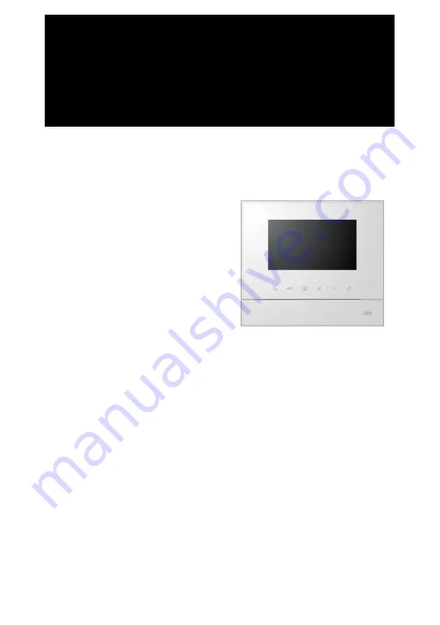
4.3" Video hands-free 

indoor station


=== Ende der  List e f ür T ext mar ke Cover ===  


Summary of Contents for M22311 Series

Page 1: ...come Pos 2 Di nA4 Anleitung en Online Inhalt KN X D oorEntr y 83220 AP xxx Titelbl att 83220 AP xxx ABB 19 mod_1323249806476_15 docx 111084 1 M22311 M22313 4 3 Video hands free indoor station Ende der Liste fü r Textmar ke Cover ...

Page 2: ...erview 13 4 3 2 Intercom call settings 14 4 3 3 Switch actuator settings 16 4 3 4 Program button settings 17 4 3 5 Call forward settings 18 4 3 6 Auto unlock settings 19 4 3 7 Outdoor station password settings 20 4 3 8 Ringtone settings 21 4 3 9 Volume settings 22 4 3 10 Date and time settings 23 4 3 11 Other settings 24 4 3 12 Blacklist settings 25 4 3 13 History review 26 4 3 14 Camera list 28 4...

Page 3: ...ly with components from this system The device must only be installed in dry indoor rooms Pos 10 Busch Jaeg er Neustr uktur Modul Struktur Online Dokumentati on Überschriften Fü r alle D okumente 1 Ebene U Z U mwelt 18 mod_1302614158967_15 docx 103383 1 1 3 Environment Pos 11 Busch Jaeg er Neustr uktur Modul Struktur Online Dokumentati on U mwel t Fü r alle D okumente Hinweise Hi nweis U mwelt Hin...

Page 4: ...gal requirements in particular the laws governing electronic and electrical devices and the REACH ordinance EU Directive 2002 96 EG WEEE and 2002 95 EG RoHS EU REACH ordinance and law for the implementation of the ordinance EG No 1907 2006 ...

Page 5: ...maler Betrieb 18 mod_1302768820965_15 docx 103540 2 1 4 1 Standard operations Pos 20 DinA4 Anl eitungen Onli ne Ueberschriften 3 Bedi enel emente 20 mod_1323260220559_15 docx 111647 3 1 4 1 1 Control elements Pos 21 DinA4 Anl eitungen Onli ne Inhalt KN X D oor Entr y 83220 AP xxx Bedi enelemente 83220 AP xxx 18 mod_1303212853605_15 docx 103673 1 Fig 1 Control elements 1 3 4 5 6 7 2 8 ...

Page 6: ...tch off the function and LED will be turned off If the LED illuminates this means auto unlock If the LED flashes rapidly it means that the door has been opened over the set time The sensor must be connected first 4 Surveillance button 4A In standby mode press this button to survey the default outdoor station 4B While the display is on press this button to the survey the next outdoor station This f...

Page 7: ...f the device If the LED flashes rapidly it means that setting is busy 8 Induction loop function For use of those buttons please contact your electrical installer The function is only available in M22313 Induction loop function This function is available for hearing impaired persons wearing a hearing aid to hear the person speaking from the outdoor station or from other indoor stations during an in...

Page 8: ... originated 3 A Press this button to survey the analog camera of the outdoor station if there is one 3 B Hold this button to take a snapshot 4 Press this button to mute the ringtone of an incoming call During a call press this button to mute the microphone 5 A Press this button to activate the function of the programmable button 5 B If the function release second lock or control switch actuator is...

Page 9: ...s during call Hold button for 3s to enter the display and volume settings menu during a call The following functions are available No Functions 1 Navigation buttons up down confirm cancel etc 2 Press the navigation buttons as needed 3 Speech volume can only be adjusted during conversation 4 Saturation 5 Brightness 6 Value set Pos 32 Busch Jaeg er Neustr uktur Modul Struktur Online Dokumentati on S...

Page 10: ...fnen 83220 AP xxx 20 mod_1323267958479_15 docx 112109 1 4 2 3 1 Overview Press button to enter the communication menu The following functions are available No Functions 1 Intercom call Click on the existing call list to make an intercom call 2 Call to guard unit Call guard unit directly 3 Broadcast Enable the broadcast function in this menu 4 Switch actuator Activate the existing actuator list 4 2...

Page 11: ...ABB Welcome 11 4 2 3 3 Call to guard unit Fig 5 Call to guard unit 4 2 3 4 Broadcast Fig 6 Broadcast call CALL GUARD UNIT Call Guard Unit BROADCAST Long pressing button to broadcast ...

Page 12: ...uator Fig 7 Switch actuator Set the actuator list in the system settings switch actuator menu first After choosing a list press button to enable the lock or light that is connected to the switch actuator SWITCH ACTUATOR Actuator 1 001 ...

Page 13: ...c unlock time range 6 Set outdoor station password Set a customized door open password which is available together with a keypad at an outdoor station 7 Ringtone Set the ringtone for outdoor bells indoor bell or others 8 Volume Set ringtone volumes 9 Date and time Set different times 10 Other settings Other settings e g auto full screen 11 Blacklist Set a blacklist that is used to prevent unwanted...

Page 14: ...he previous screen 5 Add a new intercom list A total of 32 intercom lists can be added 6 Existing intercom list Press button to modify the settings means an external intercom from different apartments For establishing an external intercom each apartment must have a master indoor station 7 Existing intercom list Press button to modify the settings means an internal intercom in the same apartment 1 ...

Page 15: ...ll within the same apartment 2 Enter to change the target address from 001 to 250 If the call type is the internal intercom there is no need to set the target address 3 Rename the intercom list Scroll through letters of the alphabet or numbers one by one with or button After setting press save tor confirm 1 Call Type External Intercom Target Address Rename 3 INTERCOM 001 mike Save Cancel 2 ...

Page 16: ... a new actuator list A total of 10 switch actuator lists can be added 3 Enter to change target address with or button from 001 to 199 4 Rename the switch actuator list Scroll through letters of the alphabet or numbers one by one with or button 3 4 SWITCH ACTUATOR Actuator 1 001 Add New Target Address Rename 002 light Save Cancel SWITCH ACTUATOR 2 1 Add a new list ...

Page 17: ...ogram button e g releasing second lock calling guard unit intercom call enabling the switch actuator Second lock means the lock is connected with an outdoor station NC NO COM Only the existing intercom call list and switch actuator list can be assigned to the program button Button 1 Release 2nd Lock PROGRAM BUTTON 1 ...

Page 18: ...se a call type including indoor or guard unit 3 Enter to change the target address if the call type is an indoor station If the call forward function is activated the auto unlock function will be disabled The function only can be set in the master indoor station 1 2 Call Forward Call Type Indoor Save Cancel CALL FORWARD Target Address 001 3 1 ...

Page 19: ... Enable disable auto unlock during Time 2 5 Set starting time and ending time for Time 2 If you activate the auto unlock function without setting exact working time this function will be available for 10 hours If the auto unlock function is activated the call forward function will be disabled The function only can be set in master indoor station 1 Auto Unlock Time 1 2 AUTO UNLOCK 08 00 17 00 Time ...

Page 20: ...r station password settings No Functions 1 Enable disable the password functions 2 Enter a 3 8 digit password only available with the keypad The function can only be set in the master indoor station 1 Enable Password Enter Password 3 8 digits SET OS PASSWORD 12345678 2 ...

Page 21: ...ion 2 Select the bell sound for other outdoor stations 3 Select the bell sound for the apartment door 4 Select the bell sound for others e g a call from the guard unit or an intercom call from other apartments 1 Default Outdoor Other Outdoors RING TONE Ring Tone 1 Ring Tone 2 2 Doorbell Ring Tone 3 Others Ring Tone 4 3 4 ...

Page 22: ...me settings No Functions 1 Set the volume of bell sound 2 Enable disable the feedback tone that sounds when the touch button is pressed 3 The ringtone can be set as fixed or cycled 1 Ringtone Volume Touchbutton Tone VOLUME Volume 3 2 Repeated Tone 3 ...

Page 23: ...3 4 3 10 Date and time settings Fig 17 Date and time settings No Functions 1 Set the date 2 Set the time 3 Enable disable the summertime function 1 Date YYYY MM DD Time DATE AND TIME 2013 2 08 Summer Time 00 01 01 3 ...

Page 24: ...ly available if sensor is installed with outdoor station flashes when the door is open 3 Enable disable the auto snapshot function The function is available in M22302 M22303 color video handset indoor station 4 Enable disable the missed call function flashes when there is a missed call 1 Auto Full Screen Auto snapshots OTHER SETTINGS 2 3 Missed Call 4 Door Status Check ...

Page 25: ...Press button to modify the settings 2 Add new blacklist s A total of 32 blacklists can be added 3 Enter to change the target address with or button from 001 to 250 The function only can be set in the master indoor station Blacklist 1 Add New BLACKLIST 001 Target Address BLACKLIST Save Cancel 002 1 2 3 ...

Page 26: ...hot function is enabled an icon will display If snapshot function is not enabled icon will not display Date time and type of the event are recorded together with the snapshot Directions means dialing calls means receiving calls HISTORY 1 2 Outdoor 1 1 63 2013 03 21 16 45 Outdoor 1 2013 03 21 16 45 Outdoor 1 2013 03 21 14 24 Outdoor 1 1 2 3 ...

Page 27: ...ABB Welcome 27 means missed calls 2 Press this button to view details of this event Two photos are always made when a visitor rings the bell 3 Press this button to delete a recorded item ...

Page 28: ...ABB Welcome 28 4 3 14 Camera list CAMERA LIST The list is disabled Outdoor1 1 Outdoor1 2 Camera1 1 2 3 CAMERA LIST Camera 1 Enable Rename Front door Visible doorbell Save Cancel 4 5 ...

Page 29: ...amera interface 3 Press this button to enable or disable camera list Default is set as disable 4 Set name of camera 1 14 characters Characters must be letters or digits 5 This option can be set only when a camera interface mode 4 is associated with this indoor station Only one camera can be set as available When the pushbutton is pressed the image from the camera connected to the camera interface ...

Page 30: ... 4 3 16 Information Fig 22 Information for outdoor station Scan QR code to get detailed instructions English LANGUAGE Franç aise Italiano Português Español Flash Version V2 07_150629 INFORMATION MCU Version V2 07_150703 M S Master Default Outdoor 1 Indoor St Add 001 ...

Page 31: ...all default configurations The operation does not delete the programmed data and history such as intercom lists and switch actuator lists 2 Clear all data Delete all programmed data and history All configurations will be restored to factory default settings Are you sure to reset RESET FACTORY DEFAULT Cancel OK Reset All Settings Clear All Data ...

Page 32: ...screen surface can be damaged by hard or sharp objects Never use such objects for entries on the touch screen monitor Use your finger or a plastic stylus The screen surface can be damaged by cleaning fluids or abrasive agents Clean the surfaces using a soft cloth and commercially available glass cleaner Never use abrasive cleaning agents Pos 69 Busch Jaeg er Neustr uktur Modul Struktur Online Doku...

Page 33: ...tdoor station 2 X10 X1 Select switches to set the address 1 99 of the indoor station X200 X100 Select dip switches to set the address hundreds digits of the indoor station 3 Master slave function Only one indoor station in each apartment should be set as master Switch should be set as M S on All additional indoor stations in the same apartment must be set as slave Switch should be set as M S off 4...

Page 34: ... docx 103705 1 Designation Value Display resolution 480 x 272 Display size 4 3 Operating temperature 10 C 55 C Storage temperature 40 C 70 C Protection IP 30 Single wire clamps 2 x 0 28 mm 2 x 0 75 mm Fine wire clamps 2 x 0 28 mm 2 x 0 75 mm Bus voltage 20 30 V Size 137 mm x 155 mm x 24 mm Pos 78 Busch Jaeg er Neustr uktur Modul Struktur Online Dokumentati on Steuermodul e Onli ne D okumentation F...

Page 35: ...7_15 docx 103564 2 1 6 1 Requirements for the electrician Warning Electric voltage Install the device only if you have the necessary electrical engineering knowledge and experience Incorrect installation endangers your life and that of the user of the electrical system Incorrect installation can cause serious damage to property such as a fire The minimum necessary expert knowledge and requirements...

Page 36: ...100 240 V wires Do not use common cables for the connecting wires of the door openers and wires of the system bus Avoid bridges between different cable types Use only two wires for the system bus in a four core or multi core cable When looping never install the incoming and outgoing bus inside the same cable Never install the internal and external bus inside the same cable Pos 83 Busch Jaeg er Neu...

Page 37: ...1302615960458_15 docx 103424 2 1 6 3 Mounting Pos 85 1 DinA4 Anl eitungen Onli ne Inhalt KN X DoorEntr y 83220 AP xxx M ontag e M odul e Montage Montagedose 83220 AP xxx 19 mod_1323250406848_15 docx 111098 1 Recommended installation height Dismantling Open the housing of the panel by pulling the clamp at the bottom of the device 1 5 meters 4 9 feet ...

Page 38: ...n instructions 2 In addition the bottom of the device can be fixed to the existing flush mounted box The dimension of the compatible flush mounted box is shown in illustration above Wiring Affix the bottom of the device and connect it in accordance with the illustration The insulated section of the cable end must not be longer than 10 mm ...

Page 39: ...rt of the device onto the bottom Place the upper side of the device on the lock in lugs and then press the bottom side onto the bottom part of the device until it is caught by the clamp 2 Mounted with flush mounted box 1 Affix the bottom of the device to the existing flush mounted box 2 Latch the upper part of the device onto the bottom part Place the upper side of the device on the lock in lugs a...

Page 40: ...device onto the bottom part Place the upper side of the device on the lock in lugs and then press the bottom side onto the bottom part of the device until it is caught by the clamp C Flush mounted Dismantling the frame For flush mounted installation dismantle the frame first 1 Mounted with back cover 1 Affix the back cover inside the wall directly ...

Page 41: ...is caught by the clamp 2 Mounted with metal flush mounted box 1 Affix the metal flush mounted box inside the wall 2 Affix the back cover to the metal flush mounted box 3 Latch the upper part of the device onto the bottom part Place the upper side of the device on the lock in lugs and then press the bottom side onto the bottom part of the device until it is caught by the clamp 3 Mounted with cavity...

Page 42: ... into the cavity wall 4 Tighten the screws 5 Latch the upper part of the indoor station onto the bottom part Place the upper side of the indoor station on the lock in lugs and then press the bottom side onto the bottom part of the device until it is caught by the clamp Replacing the front cover The installation of the indoor station is now complete Pos 94 Busch Jaeg er Neustr uktur Modul Struktur ...

Page 43: ...r We reserve the right to at any time make technical changes or changes in the content of this document without prior notice The detailed specifications agreed to at the time of ordering applies to all orders ABB accepts no responsibility for possible errors or incompleteness in this document We reserve all rights to this document and the topics and illustrations contained therein The document and...

Reviews: