


19
KM26 |
MAGNETIC LEVEL GAUGE | OI/KM26-EN REV I
The installation of insulation on KM26 units is dependent
upon the process temperatures and type of indicator used.
All temperatures referenced in insulation instructions refer to
process temperatures. For design temperature under 200 °F,
no insulation is required. If ordered, the insulation will be a
tied-on blanket (standard insulation attached to the scale
assembly). For 300 °F to 450 °F, an insulation pad is required
for magnetic bargraph (MBG) indication. If chamber
insulation is ordered in lieu of insulation pad, then the
insulation will be a pipe wrap blanket. For 450 °F to 500 °F,
pipe wrap blankets are mandatory for MBG indication. Before
installing any blanket or pad, note the location of all chamber
accessories to ensure a return to the proper working location.
Some units are built with limited accessory locations and the
accessories may not function if moved to new location.
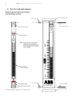
. . . 3 Mounting
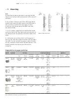
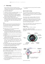
Figure 22 - side and front view of pipe wrap
Edges of the scale assembly can be sharp. Gloves and
proper care are required while working.
CAUTION
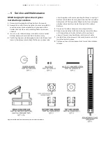
Insulation pads
To install insulation pads, simply remove the accessory from
the unit. Set the accessory on the pad. Using a razor, cut a
hole through the pad wherever a bracket or clamp exists.
Push the brackets or clamps through the hole and re-attach
the accessory to the previous location. Verify proper
operation and location.
The insulation thickness of a blanket is determined by the
process temperature. In all locations where scale indications,
switches, and transmitters are located, the insulation
thickness is thinned to ½ in. to facilitate magnetic coupling.
For all other locations the insulation thickness it governed by
the following:
• 0 to 250 °F (0 to 121 °C) ½ in. thickness ceramic fiber filler
with inner and outer silicone impregnated cloth covering
• 251 to 500 °F (122 to 260 °C) 1 in. thickness ceramic fiber
filler with inner and outer silicone impregnated cloth
covering
• 501 to 850 °F (261 to 454 °C) 1 in. thickness ceramic fiber
filler with outer silicone impregnated cloth covering and
4-ply high temp liner including TempKoat™ insulation
• 851 to 1000 °F (455 to 538 °C) 2 in. thickness ceramic fiber
filler with outer silicone impregnated cloth covering and
4-ply high temp liner including TempKoat™ insulation
For insulated units, it is critical to know the location of all
components attached to the unit when ordering the
insulation. Typically, the scale is located opposite to the
process connections and the insulation will be thinned down
to ½ in. on that side. If the scale has been moved from the
position that it is shipped in, then the thinned insulation will
not be in the correct location. When ordering, ABB refers to
location by a clock system with the process connections at 12
o’clock when looking down on the unit from above. The scale
is typically at 6 o’clock. Openings for the connections are
made on the basis of the orientation specified by the
customer. Thinning of insulation is needed for switches and
transmitters as well and their positions must also be known.
Pipe wrap blanket
For pipe wrap blankets, installation requires the removal of
scale assembly and transmitter (if installed). If a transmitter
is installed, note its location and undo the front of the
brackets (not the gear clamps) and remove the transmitter.
Switches on switch mount rods will have to be rotated away
from the chamber. Wrap the insulation blanket around the
unit and fasten it with the Velcro straps. If a transmitter was
installed, feel for the brackets under the insulation and mark
their location with a marker. Sew a 1 in. square through the
blanket around the marks. Using a razor, cut an X from corner
to corner of the square making sure not to break the new
seam. Push the brackets through the new holes. Set the
scale assembly against the insulation at proper mounting
location. Draw a mark on each side of each gear clamp next
to the scale channel. This location on the insulation should
have sewn seams down the length of the blanket to prevent
fraying. It is recommend that the marks for each clamp be
sewn around to reduce fraying. Using a razor, cut through the
insulation to allow the gear clamp to pass through the hole.
Once a hole is made for each clamp, remove the blanket from
the unit. Feed the gear clamps of the scale assembly through
the holes so that each end of the clamp goes through. Set
the scale assembly and insulation blanket against the unit
and use the gear clamps to fasten the parts to the unit. Make
sure that the screw for the clamp does not interfere with the
transmitter or switch locations. If applicable, feed the
brackets for the transmitter through their holes in the
blanket. Attach the velcro closures on the back of the blanket.
Rotate any switches back into position. Re-attach the
transmitter at the proper location. Verify the operation of all
devices. An inoperative switch may need to be pressed
tighter to the unit. Transmitters should be checked for the
correct zero point and slid up or down to set to proper level.
Insulation instructions


