


14
KM26 |
MAGNETIC LEVEL GAUGE | OI/KM26-EN REV I
. . . 3 Mounting
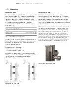
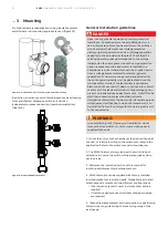
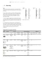
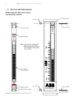
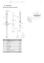
For high temperature applications using insulation jackets
and alternate rod mounting approach is used (figure 15).
In addition, alternative switch technologies, such as vibrating
forks and thermal dispersion switches require an
independent process connection (chamber penetration).
(figure 16).
Figure 15 - MLG switch with insualtion jacket with rod mounting
Figure 16 - MLG with RS85/TX switches
CAUTION: OPEN CIRCUIT BEF
ORE REMOVING COVER
ATTENTION: OUVRIR LE CIRCUIT
AVANT D'ENLEVER LE COUVERCL
E
MAX PRESSURE: 2000 PSI; VMAX:
36VDC; RELAY IMAX: 8A
AMB.TEMP - HOUSING: -40°C
TO +66°C; SENSOR:
MODEL NO:
TAG NO:
Ex d IIC T6 Ga/Gb [-40°C ≤ T
amb ≤ 50°C]
Ex ta IIIC T150 Da [-40°C ≤Ta
mb ≤ 66°C]
K-TEK PRODUCTS
SERIAL NO:
MADE IN USA LOUISI
ANA, 70769 TAG
0123
ITS13ATEX17811X
IECEx ITS 14.0051X
0575
IP66/67
! SEE MANUAL
II 1 D
II 1/2 G
Ex d IIC T5 Ga/Gb [-40°C ≤ T
amb ≤ 66°C]
CAUTION: OPEN CIRCUIT BEF
ORE REMOVING COVER
ATTENTION: OUVRIR LE CIRCUI
T AVANT D'ENLEVER LE COUV
ERCLE
MAX PRESSURE: 2000 PSI; VMA
X: 36VDC; RELAY IMAX: 8A
AMB.TEMP - HOUSING: -40°C
TO +66°C; SENSOR:
MODEL NO:
TAG NO:
Ex d IIC T6 Ga/Gb [-40°C ≤ T
amb ≤ 50°C]
Ex ta IIIC T150 Da [-40°C ≤Tamb
≤ 66°C]
K-TEK PRODUCTS
SERIAL NO:
MADE IN USA LOUISIANA,
70769 TAG0123
ITS13ATEX17811X
IECEx ITS 14.0051X
0575
IP66/67
! SEE MANUAL
II 1 D
II 1/2 G
Ex d IIC T5 Ga/Gb [-40°C ≤ Tamb
≤ 66°C]
in.
3
6
3
1
ft.
9
9
6
in.
3
6
3
1
ft.
9
9
6
in.
3
6
3
1
ft.
9
9
6
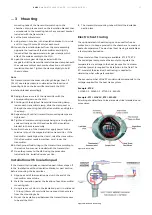
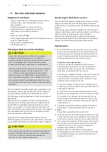
In an explosion-proof / flame-proof installation, do not
remove the transmitter or switch covers when power is
supplied to the unit.
WARNING
Observe all applicable regulations governing electrical
installation. Connections must be established only in a
zero-voltage state. Since the transmitter or the switches
do not switch-off elements, overvoltage protection
devices, lightning protection and / or voltage separation
capacity must be provided at the plant. Check that the
existing operating voltage corresponds to the voltage
indicated on the name plate. In case the surge protection
option is present and the transmitter is installed in a
hazardous area, the transmitter has to be supplied power
from a voltage source isolated from mains (galvanic
separation). Furthermore, the potential equalization for
the entire powering cable must be guaranteed since the
intrinsic safety circuit of the transmitter is grounded.
Electrical shock can result in death or serious injury. Avoid
contact with the leads and terminals. High voltage can be
present on leads and cause electrical shock. Do NOT make
electrical connections unless the electrical code
designation stamped on the transmitter data plate agrees
with the area classification in which the transmitter is to
be installed. Failure to comply with this warning can result
in fire or explosion.
DANGER
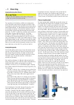
General installation guidelines
1. Mount the switch to the chamber at the desired trip point.
Connect or terminate wiring to the switch according to the
application. Refer to the switch manual wiring diagram.
2. The KM26 float must be cycled past the switch in both
directions to ensure the switch will operate properly when
put in service.
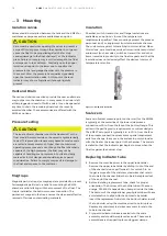
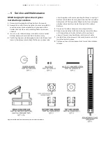
3. Reference the insulation section of this manual for
installing and dismantling insulation jackets.
4. KM26 chambers can be supplied with factory installed
insulation jackets or insulation pads. Magnetically actuated
switches can be mounted in two different configurations.
• if an insulation jacket is used, rod mount brackets are
required.
• if insulation pads are used, stainless steel gear clamps
are required.
5. These adjustable brackets and clamps allow re-positioning
this switch at any point along the measuring range of the
level gauge.


