


1 Description
1.6.1 Introduction
3HAC9117-1
Rev.N
37
IRB 4400/L10
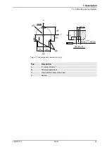
Figure 20 The shaded area indicates the permitted positions (center of gravity) for any extra equipment
mounted in the holes (dimensions in mm).
Pos
Description
A
M6 (2x) Depth of thread 9
B
M8 (3x) Depth of thread 14
E
M8 (3x), R=92 Depth 16
(If option 34-1 is chosen these holes are occupied.)
110
115
77
38.
5
150
300
150
390
20
o
B
B
B - B
A
A - A
250
175
A
Max. 15 kg
54
Max. 2 kg
110
25
43
D=240 22
78
300
1221
M5 (2x)
120
o
(3x)
15
o
C - C
C
C
D=100
195
Max. 35 kg
(A)
(B)
(C)
Summary of Contents for IRB 4400/45
Page 2: ......
Page 6: ...Table of Contents 4 Rev N 3HAC9117 1 ...
Page 54: ...1 Description 1 8 5 Signals 52 Rev N 3HAC9117 1 ...
Page 64: ...3 Accessories 62 Rev N 3HAC9117 1 ...
Page 66: ...Index 64 Rev N 3HAC9117 1 ...
Page 67: ......


