Page 6
© 2021 ABB. All rights reserved.
QUICK START GUIDE
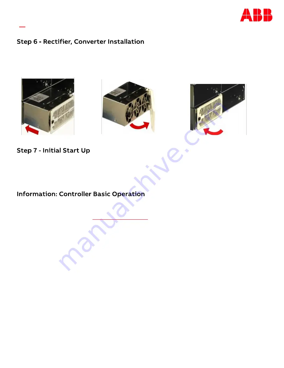
Slide the rectifier/converter
into the slot approximately
3/4 of the way.
Verify all AC, DC, Alarm and system interface connections are complete and secure. If rectifiers have not yet been
installed, install rectifiers now as described previously. Once this is complete turn on the AC input breakers. As each
rectifier is installed, the controller automatically identifies the new rectifier and begins communication. If there are
no alarms, make adjustments to the default settings on the controller as required for this installation. Using the
front panel menu to configure settings and functions is intuitive. Refer to the menu map on the next page.
Viewing and changing system parameters from the factory defaults can be accomplished in several ways; A) front
display, B) Craft Port on front of controller using a laptop with EasyView2 or HyperTerminal. EasyView2 (GUI)
software can be downloaded from
, C) J5 LAN port in Static, Client, or Server mode. Static
and Client modes are for accessing web pages through a network. Server mode allows local access to the controller
web pages directly from a laptop connected to J5 LAN port; Menu>Configure>Communication Ports>Network
Settings>DHCP (Server). Server mode default IP address is 192.168.2.1. With the controller set to Server type the
default IP address in the web browser address field. Server mode is a temporary setting, once configuration is
complete reset the controller to Client or Static before connecting to the network. Static is the factory default
setting and the typical setting for most networks. Warning: Do not connect J5 LAN port to a network when set to
Server.
Controller Alarm Status: The display changes colors; Green = Normal, Amber = Minor Alarm, Red = Critical/Major
Alarm
Some alarms may occur during initial installation; example: thermal probe fail or Major/Minor communication fail .
To clear these alarms from the Controller Display: follow the menu path; Menu > Control/Operation > Clear Events or
Uninstall Equipment.
Using web pages or EasyView2; Select the Maintenance tab > clear latched events and clear missing devices.
Verify Basic Installation Settings: To verify Date, Time, Battery Type, number of strings and float voltage for this
application using the Controller Display: follow the menu path; Menu > Configuration > System Settings and Menu >
Configuration > Batteries. Using web pages or EasyView2; Select the Installation Tab to set the Date, Time. Site ID
and Site Description. Select the Settings Tab > Battery Management to verify Battery Type and set number of
battery strings installed.
Open the faceplate by sliding the
face
-
plate latch to the left until the
faceplate releases and swings outward.
Slide the unit into the slot until it engages
with the back of the shelf. Swing the
faceplate closed to seat the rectifier/
converter. Verify the faceplate is latched.


